Mazda CX-7 Service Repair Manual
2007 Mazda CX-7 Workshop Manual
This manual contains on-vehicle service and/or diagnosis procedures for the Mazda CX-7. For proper repair and maintenance, a thorough familiarization with this manual is important, and it should always be kept in a handy place for quick and easy reference.
ON-BOARD DIAGNOSTIC [L3 WITH TC]
FOREWORD[L3 WITH TC]
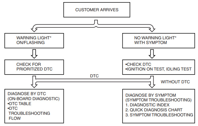
When the customer reports a vehicle malfunction, check the malfunction indicator lamp (MIL) indication and diagnostic trouble code (DTC), then diagnose the malfunction according to the following flowchart.
- If a DTC exists, diagnose the applicable DTC inspection. (See 01-02-13 DTC TABLE[L3 WITH TC].)
- If a DTC does not exist and the MIL does not illuminate or flash, diagnose the applicable symptom troubleshooting. (See 01-03-8 QUICK DIAGNOSTIC CHART[L3 WITH TC].)
OBD-II PENDING TROUBLE CODE[L3 WITH TC]
These appear when a problem is detected in a monitored system. The code for a failed system is stored in the PCM memory in the first drive cycle. This code is called the pending code. If the PCM determines that the system has returned to normal or the problem was mistakenly detected, it deletes the pending code. If the problem is found in the second drive cycle, too the PCM determines that the system is malfunctioning, and the DTC is stored.
OBD-II FREEZE FRAME DATA[L3 WITH TC]
This is technical data which indicates the engine condition at the time of the first malfunction. This data will remain in the memory even if another emission-related DTC is stored, with the exception of the Misfire or Fuel System DTCs. Once freeze frame data for the Misfire or Fuel System DTC is stored, it will overwrite any previous data and the freeze frame will not be overwritten again.
OBD-II ON-BOARD SYSTEM READINESS TEST[L3 WITH TC]
This shows the OBD-II systems operating status. If anymonitor function is incomplete, the M-MDS will identifywhich monitor function has not been completed. Misfires, Fuel System and Comprehensive Components(CCM) are continuous monitoring-type functions. The catalyst, EGR system, evaporation system and oxygensensor will be monitored under drive cycles. The OBD-II diagnostic system is initialized by performing the DTCcancellation procedure or disconnecting the negative battery cable.
OBD-II READ/CLEAR DIAGNOSTICTEST RESULTS[L3 WITH TC]
This retrieves all stored DTCs in the PCM and clears the DTC, Freeze Frame Data, On-Board Readiness TestResults, Diagnostic Monitoring Test Results and Pending Trouble Codes.
OBD-II PARAMETER IDENTIFICATION(PID) ACCESS[L3 WITH TC]
The PID mode allows access to certain data values, analog and digital inputs and outputs, calculated valuesand system status information. Since PID values for output devices are PCM internal data values, inspect eachdevice to identify which output devices are malfunctioning.
OBD-II DIAGNOSTIC MONITORINGTEST RESULTS[L3 WITH TC]
These result from the intermittent monitor system technical data, which are used to determine whether the system is normal or not. They also display the system’s thresholds and diagnostic results. The intermittent monitor system monitors the oxygen sensor, EVAP purge system, catalyst and the EGR system.
ON-BOARD DIAGNOSTIC TEST[L3 WITH TC]
DTC Reading Procedure
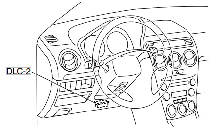
- Connect the M-MDS to the DLC-2.
- After the vehicle is identified, select the followingitems from the initial screen of the M-MDS.
- When using the IDS (notebook PC)
- Select the “Toolbox” tab.
- Select “Self Test”.
- Select “Module”.
- Select “PCM”.
- When using the PDS (pocket PC)
- Select “Module Tests”.
- Select “PCM”.
- Select “Self Test”.
- Then, select the “Retrieve CMDTCs” and performa procedures according to directions on the M-MDS screen.
- Verify the DTC according to the directions on the M-MDS screen.
- If any DTCs are displayed, perform troubleshooting according to the corresponding DTC inspection.
- After completion of repairs, clear all DTCs stored in the PCM, while referring to “AFTER REPAIR PROCEDURE“.
Pending Trouble Code Access Procedure
- Connect the M-MDS to the DLC-2.
- After the vehicle is identified, select the followingitems from the initial screen of the M-MDS.
- When using the IDS (notebook PC)
- Select the “Toolbox” tab.
- Select “Self Test”.
- Select “Module”.
- Select “PCM”.
- When using the PDS (pocket PC)
- Select “Module Tests”.
- Select “PCM”.
- Select “Self Test”.
- Then, select the “Retrieve CMDTCs” and perform procedures according to directions on the M-MDS screen.
- Retrieve the pending trouble codes according to the directions on the M-MDS screen.
Freeze Frame PID Data Access Procedure
- Connect the M-MDS to the DLC-2.
- After the vehicle is identified, select the followingitems from the initial screen of the M-MDS.
- When using the IDS (notebook PC)
- Select the “Toolbox” tab.
- Select “Self Test”.
- Select “Module”.
- Select “PCM”.
- When using the PDS (pocket PC)
- Select “Module Tests”.
- Select “PCM”.
- Select “Self Test”.
- Then, select the “Retrieve CMDTCs” and perform procedures according to directions on the M-MDSscreen.
- Retrieve the freeze frame PID data according to the directions on the M-MDS screen.
On-Board System Readiness Tests Access Procedure
- Connect the M-MDS to the DLC-2.
- After the vehicle is identified, select the followingitems from the initial screen of the M-MDS.
- When using the IDS (notebook PC)
- Select the “Toolbox” tab.
- Select “Powertrain”.
- Select “OBD Test Modes”.
- Select “Mode 1 Powertrain Data”.
- When using the PDS (pocket PC)
- Select “OBD II Modes”.
- Select “Mode 1 Powertrain Data”.
- Then, select the “***SUP” and “***EVAL” PIDs in the PID selection screen.
- Monitor those PIDs and check it system monitor iscompleted.
PID/DATA Monitor and Record Procedure
Note
The PID/DATA MONITOR function monitors the calculated value of the input/output signals in the PCM.Therefore, an output device malfunction is not directly indicated as a malfunction of the monitored value for the output device. If a monitored value of an output device is out of specification, inspect the monitored value of the input device related to the output control.
- Connect the M-MDS to the DLC-2.
- After the vehicle is identified, select the followingitems from the initial screen of the M-MDS.
- When using the IDS (notebook PC)
- Select the “Toolbox” tab.
- Select “DataLogger”.
- Select “Module”.
- Select “PCM”.
- When using the PDS (pocket PC)
- Select “Module Tests”.
- Select “PCM”.
- Select “DataLogger”.
- Select the PID from the PID table.
- Verify the PID data according to the directions onthe screen.
Diagnostic Monitoring Test Results Access Procedure
- Connect the M-MDS to the DLC-2.
- After the vehicle is identified, select the followingitems from the initial screen of the M-MDS.
- When using the IDS (notebook PC)
- Select the “Toolbox” tab.
- Select “Powertrain”.
- Select “OBD Test Modes”.
- Select “Mode 6 On-Board Test Results”.
- When using the PDS (pocket PC)
- Select “OBD II Modes”.
- Select “Mode 6 On-Board Test Results”.
- Verify the diagnostic monitoring test result according to the directions on the screen.
Simulation Function Procedure
- Connect the M-MDS to the DLC-2.
- After the vehicle is identified, select the followingitems from the initial screen of the M-MDS.
- When using the IDS (notebook PC)
- Select the “Toolbox” tab.
- Select “DataLogger”.
- Select “Module”.
- Select “PCM”.
- When using the PDS (pocket PC)
- Select “Module Tests”.
- Select “PCM”.
- Select “DataLogger”.
- Select the simulation items from the PID table.a
- Perform the simulation function, inspect theoperations for each parts.
- If there is no operation sound from the relay, motor, and solenoid after the simulation function inspection is performed, it is possible that there is an open or short circuit in the wiring harness, relay, motor or solenoid,or sticking and operation malfunction.
DIAGNOSTIC MONITORING TEST RESULTS[L3 WITH TC]
The purpose of this test mode is to confirm the result of the OBD-II monitor diagnostic test results. The result values stored when a particular monitor is completed are displayed. If the monitor is not completed, the initial value is displayed.
AFTER REPAIR PROCEDURE[L3 WITH TC]
- Connect the M-MDS to the DLC-2.
- Cycle the ignition switch from the off to the ON position.
- Any retrieved DTCs.
- Clear all diagnostic data using the M-MDS.
KOEO/KOER SELF TEST[L3 WITH TC]
- Perform the necessary vehicle preparation and visual inspection.
- Connect the M-MDS to the vehicle DLC-2 16-pin connector located in the driver compartment.
- Retrieve the KOEO/KOER DTCs using the M-MDS.
OBD-II DRIVE MODE[L3 WITH TC]
- Using the OBD-II drive mode, the monitoring item requested by OBD-II regulations can be easily diagnosed.
- Performing the Drive Mode inspects the OBD-II system for proper operation and must be performed to ensure that no additional DTCs are present.
- The OBD-II drive mode is divided into the specific drive mode and single drive mode.
- For the specific drive mode, specified drive modes havebeen set for each individual monitoring item requested by OBD-II regulations, and they can be diagnosed individually. For the single drive mode, the entire monitoring item requested by OBD-II regulations can be diagnosed.
- The following modes are in the specific drive mode. The applicable system is diagnosed by driving in the following drive modes.
- PCM Adaptive Memory Produce Drive Mode
- EGR System Repair Verification Drive Mode
- HO2S heater, HO2S, and TWC Repair Verification Drive Mode
- EVAP System Repair Verification Drive Mode
- The following systems are diagnosed with the single drive mode.
- EGR system
- Oxygen sensor (HO2S)
- Oxygen sensor heater
- Catalytic converter (TWC)
- Fuel, misfire and evaporative (EVAP) system
Caution
- While performing the Drive Mode, always operate the vehicle in a safe and lawful manner.
- When the M-MDS is used to observe monitor system status while driving, be sure to have another technician with you, or record the data inthe M-MDS using the PID/DATA MONITOR AND RECORD function and inspect later.
Note
- Vehicle speed and engine speed detected by the PCM may differ from that indicated by the speedometer and tachometer. Use the M-MDS to monitor vehicle speed.
- If the OBD-II system inspection is not completed during the Drive Mode, the following causes are considered:
- The OBD-II system detects the malfunction.
- The Drive Mode procedure is not completed correctly.
- Disconnecting the battery will reset the memory. Do not disconnect the battery during and after Drive Mode.
- The M-MDS can be used at anytime through the course of the Drive Mode to monitor the completion status. Monitoring can be done by viewing the ON BOARD SYSTEM READINESS menu.
- The OBD monitoring status can be confirmed with the ignition switch operation. During KOEO, the MIL illuminates for a fail-light inspection forapprox. 17 s. The OBD monitoring status is confirmed after the fail-light inspection.
- If all of the diagnosis is completed even one time, the MILwill continue to illuminate.
- If all of the diagnosis is not completed, the MIL flashes forapprox. 7 s, and then it illuminates until the engine is started.
EGR System Repair Verification Drive Mode
- Perform “PCM Adaptive Memory Production Drive Mode” first.
- Verify all accessory loads (A/C, headlights, blower fan, rear window defroster) are off.
- Drive the vehicle as shown in the graph.
- Stop the vehicle and access ON BOARDSYSTEM READINESS menu of GENERIC OBD-II FUNCTION to verify the OBD monitoring status.
- If completed, the OBD monitoring statusitems change from non-completed tocompleted.
- If not completed, turn the ignition switch offthen repeat from Step 3.
- Access DIAGNOSTIC MONITORING TESTRESULTS menu of GENERIC OBD-IIFUNCTIONS to verify the monitor results.
- If detected values are not within specification,repair has not been completed.
- Verify no DTCs are available.
HO2S heater, HO2S, and TWC Repair Verification Drive Mode
- Perform “PCM Adaptive Memory Production Drive Mode” first.
- Verify all accessory loads (A/C, headlights, blower fan, rear window defroster) are off.
- Drive the vehicle as shown in the graph. The driving conditions before driving at constant speed are notspecified.
- Stop the vehicle and access ON BOARD SYSTEM READINESS menu of GENERIC OBD-II FUNCTION toverify the OBD monitoring status.
- If completed, the OBD monitoring status items change from non-completed to completed.
- If not completed, turn the ignition switch off then repeat from Step 3.
- Access DIAGNOSTIC MONITORING TEST RESULTS menu of GENERIC OBD-II FUNCTIONS to verify the monitor results.
- If detected values are not within the specification, repair has not been completed.
- Verify no DTCs are available.