Mazda Miata Factory Repair Manual
Mazda Miata 1991-2009 Factory Service Manuals
1991 Mazda MX-5 Miata
AUTO TRANS OVERHAUL - N4A-EL, N4A-HL & NC4A-EL AUTOMATIC TRANSMISSIONS Mazda N4A-EL N4A-EL & NC4A-EL
| Vehicle Application | Labor Times (1) R&I | Labor Times (2) Overhaul | Trans. Model |
| Miata | |||
| 1990-93 | 4.9 | 8.6 | N4A-HL |
| 1994 | 4.9 | 8.6 | NC4A-EL |
| MPV (1989-94 w/2.6L) | 3.9 | 8.6 | N4A-HL |
| RX7 (1989-91) | 3.4 | 8.6 | N4A-EL |
| 929 (1988-91) | 3.3 | 9.1 | N4A-EL |
(1) Removal and installation of transmission from vehicle chassis.
(2) On bench overhaul for transmission. DOES NOT include removal and installation.
IDENTIFICATION
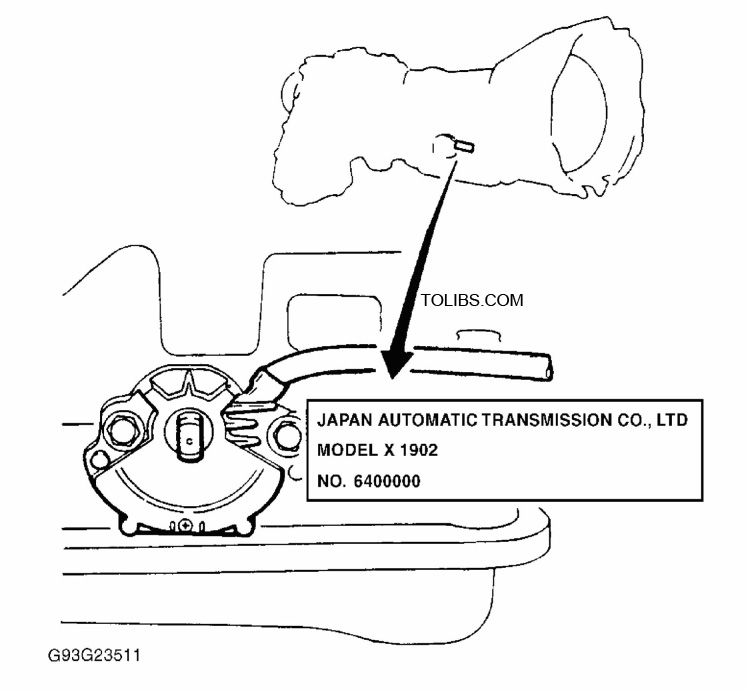
This transmission is manufactured by Japan Automatic Transmission Company (JATCO). Transmission model may be identified by a stamped metal plate attached to right side or top of transmission case. Plate lists model code on second line and serial number on bottom line.
Locating Service Identification Tag
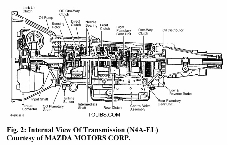
DESCRIPTION
N4A-HL and N4A-EL components may vary. All are 4-speed overdrive units, controlled either hydraulically or electrically. These units have 3-element lock-up torque converters and 3 planetary gear sets. N4A-EL uses a computer to select shift patterns (standard or power) depending upon accelerator position. Shift pattern programs are set in lock-up control unit according to vehicle speed and throttle position.
LUBRICATION & ADJUSTMENTS
See the appropriate TRANSMISSION SERVICING article. Refer to the following menu:
- For 1991 models, see TRANSMISSION SERVICING - A/T .
- For 1992 models, see TRANSMISSION SERVICING - A/T .
ON-VEHICLE SERVICE
See the appropriate TRANSMISSION SERVICING article:
- For 1991 models, see TRANSMISSION SERVICING - A/T article.
- For 1992 models, see TRANSMISSION SERVICING - A/T article.
TROUBLESHOOTING
For electronic control system troubleshooting, refer to the AUTO TRANS DIAGNOSIS - N4A-EL/HL & NC4A-EL article in this section.
Mazda MX-5 Miata Engines 1.6L 4-Cylinder - VIN (1)
ENGINE IDENTIFICATION
NOTE: For engine repair procedures not covered in this article, see ENGINE OVERHAUL PROCEDURES - GENERAL INFORMATION article in the GENERAL INFORMATION section.
Engine may be identified by Vehicle Identification Number (VIN). VIN is stamped on a metal pad located near lower left comer of windshield. The eighth character identifies the engine model. Engine can also be identified by engine number. On Miata, engine number is stamped on flange, at upper right rear of cylinder block deck as viewed from flywheel.
| Application | Engine Code | VIN Code |
| 1.6L 4-Cylinder DOHC | B6 | 1 |
VALVE CLEARANCE ADJUSTMENT
NOTE: Valve clearance is not adjustable. Some valve noise may occur during engine start-up. Noise should disappear after engine reaches normal operating temperature. If noise persists, check oil pressure, oil level and engine condition.
TROUBLE SHOOTING
NOTE: To trouble shoot engine mechanical components, see appropriate table in TROUBLE SHOOTING article in GENERAL INFORMATION.
REMOVAL & INSTALLATION
NOTE: For reassembly reference, label all electrical connectors, vacuum hoses and fuel lines before removal. Also place mating marks on engine hood and other major assemblies before removal.
FUEL PRESSURE RELEASE
Disconnect circuit opening relay, located behind lower dash, left of steering column. Start engine and allow to idle until it stalls. Turn ignition off. Disconnect negative battery cable, and reconnect circuit opening relay. When disconnecting fuel hoses, cover connection with shop rag to catch fuel spray.
NOTE: On Miata audio anti-theft system, radio will not operate if power is cut to radio, obtain code number from customer to reactivate radio. To reactivate radio after reconnecting power supply, turn ignition switch to ACC position, press and hold FF and REW buttons until cod e is displayed. Again press and hold FF and REW buttons until bars (--- -) are displayed. Use preset button No. 1 to enter first number. Use preset buttons No. 2 to enter second number, 3 for third number, ect. Press FF and REW buttons for about 2 seconds until a beep is heard. After 5 seconds, flashing "cod e" will go away and radio will operate.
Removing & Installing Drive Train Components
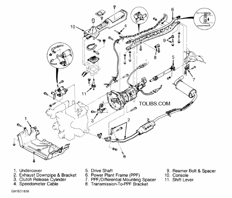
- Relieve fuel pressure. See FUEL PRESSURE RELEASE under REMOVAL & INSTALLATION. Disconnect negative battery cable from trunk-mounted battery. Reference mark hood and remove. Raise vehicle, and remove engine undercover. See Fig. 1 . Drain engine oil, transmission oil and cooling system.
- Disconnect exhaust manifold downpipe and exhaust bracket bolts. On A/T models, disconnect shift rod linkage at transmission. On M/T models, remove clutch release cylinder from clutch housing, DO NOT disconnect fluid line.
- On all models, note location and remove transmission wiring harness connectors and speedometer cable. Match mark rear drive shaft flanges, and remove drive shaft.
- Push up on transmission, and remove Power Plant Frame (PPF) angle bracket from lower rear of transmission extension housing. Remove 4 PPF long mounting bolts from transmission and differential, noting location of large shank reamer bolt at differential. Remove PPF/differential mounting spacer bolts, and pry out spacer at differential. See Fig. 3 . Remove engine mount nuts.
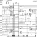
- Lower vehicle. On M/T models, remove shift knob, center console, boot and transmission shift lever. See Fig. 1 . On all models, remove air cleaner assembly and throttle body intake duct assembly. See Fig. 2 . Remove throttle cable.
- Remove all cooling system hoses and A/T oil cooler lines at radiator (if equipped). Remove radiator and cooling fans as an assembly. Remove all drive belts. DO NOT disconnect power steering hoses or A/C compressor hoses. Remove power steering pump and A/C compressor from engine, and secure units away from engine.
- Note locations of and disconnect all necessary electrical connectors, ground wires, vacuum hoses, fuel hoses, coolant hoses and control cables for engine removal. Plug all fuel hoses to prevent leakage. Remove engine and transmission as an assembly. Remove starter after engine is removed from vehicle.
NOTE: Proper installation of PPF is critical for aligning drive shaft, and eliminating harmonic vibrations.
Installation
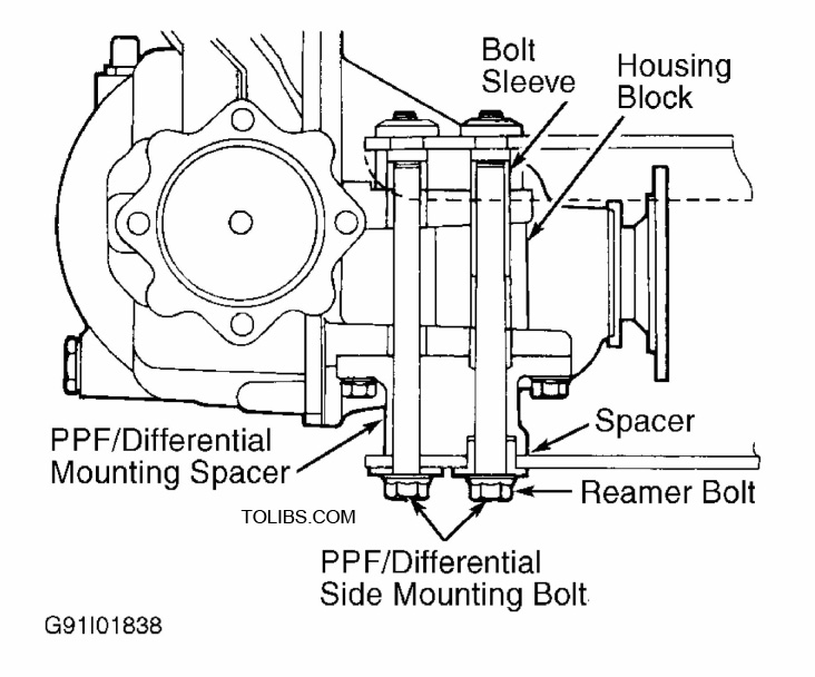
- To install, reverse removal procedure. After installing engine mount nuts, mount PPF to transmission, and tighten long bolts by hand. Ensure bolt sleeve and PPF/differential mounting spacer are installed to differential housing block.
- Tighten PPF/differential mounting spacer bolts to 27-38 ft. lbs.(37-52 N.m). See Fig. 3 . Install PPF to differential. Hand-tighten longbolts. Ensure PPF-to-differential large shank reamer bolt and spacer are properly installed. NOTE: Reamer bolt is the front long bolt attaching PPF to differential. This bolt aligns PPF with drive train.
- When PPF is properly aligned between transmission and differential, tighten all long mounting bolts to specification. Install rear transmission-to-PPF bracket, and tighten to specification. See TORQUE SPECIFICATIONS. To complete installation, reverse removal procedure. Before installing M/T shift lever, add gear oil to transmission through shifter hole. Fill all fluids to correct levels.
Locating PPF-To-Differential Reamer Bolt, Sleeve & Spacer
INTAKE MANIFOLD Removal
- Relieve fuel pressure. See FUEL PRESSURE RELEASE. Disconnect negative battery cable. Drain cooling system. Remove air cleaner assembly and ducting. See Fig. 2 . Mark and disconnect coolant hoses, vacuum hoses and electrical connectors from intake manifolds.
- Disconnect throttle cable. Remove fuel lines from fuel rail and pressure regulator. Remove throttle body intake duct housing and throttle body. Remove air valve.
- On all models, remove intake manifold support bracket from underneath manifold. Disconnect injector harness connectors, and remove injectors/fuel rail assembly. Remove intake manifold and gasket.
INTAKE MANIFOLD Removal Installation
- Ensure all gasket surfaces are clean and flat. Install NEW gasket and intake manifold to cylinder head. Tighten manifold bolts/nuts evenly to specification, starting from center bolt and alternating outward. See TORQUE SPECIFICATIONS. Install support bracket underneath intake manifold.
- Install gasket and upper intake manifold (if equipped). Tighten bolts/nuts evenly to specification, alternating from top to bottom. See TORQUE SPECIFICATIONS. 3. To complete installation, reverse removal procedure. Ensure Throttle cable has .04-.12" (1-3 mm) free play. Ensure injectors twist freely and are not cocked in insulator "O" rings. Refill engine with coolant.
EXHAUST MANIFOLD Removal & Installation
- Disconnect oxygen sensor. Remove heat shields. Disconnect downpipe from exhaust manifold. Remove exhaust manifold.
- To install, reverse removal procedure. Ensure all mating surfaces are clean and flat. Install NEW gasket to cylinder head. Tighten manifold bolts evenly to specification, starting from center bolt and alternating outward. See TORQUE SPECIFICATIONS.
CYLINDER HEAD Removal
- Drain engine coolant. Release fuel pressure. See FUEL PRESSURE RELEASE under REMOVAL & INSTALLATION. Remove exhaust and intake manifolds.
- Note locations and disconnect all necessary electrical connectors, ground wires, vacuum hoses, fuel hoses, coolant hoses and control cables for cylinder head removal. Plug all fuel hoses to avoid leakage.
- Remove spark plug wires from spark plugs. Remove all drive belts. Remove water pump pulley. Remove timing belt. See TIMING BELT. Remove camshaft/rocker cover.
- Remove front exhaust pipe. Remove intake manifold support bracket. Loosen all cylinder head bolts evenly in sequence, in 2-3 steps. See Fig. 2 . Remove bolts and cylinder head assembly.
See Mazda Miata MX-5 1991-2008 brochure Document here