Mazda Millenia Workshop Manual

1996 Mazda Millenia Workshop Manual
FOREWORD
A thorough familiarization with this manual is important for proper repair and maintenance. It should always be kept in a handy place for quick and easy reference.
The contents of this manual, including drawings and specifications, are the latest available at the time of printing. As modifications affecting repair or maintenance occur, relevant information supplementary to this volume will be made available at Mazda dealers. This manual should be kept up-to-date.
VEHICLE IDENTIFICATION NUMBERS (VIN)
JM1 TA22KT1 200001
JM1 TA222*T1 200001
RELATED MATERIALS
- MILLENIA Service Highlights 9999-95-095F-95
- 1996 Protege, MX-3, MX-5, 626/MX-6, 929,
- MPV, Millenia Service Highlights 9999-95-MODL-96
- MILLENIA Wiring Diagram 9999-95-036G-96
- Engine Workshop Manual KL 9999-95-EWKL-95
- Engine Workshop Manual KJ 9999-95-EWKJ-95
- ATX Workshop Manual GF4A-EL 9999-95-GF4A-95
- ATX Workshop Manual LJ4A-EL 9999-95-LJ4A-95
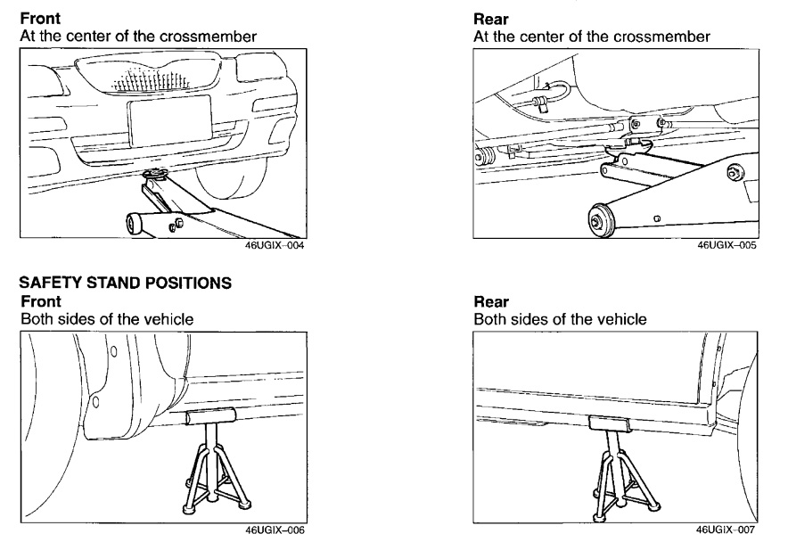
JACKING POSITIONS
- Warning: Improperly jacking a vehicle is dangerous. The vehicle can slip off the jack and cause serious injury. Use only the correct front and rear jacking positions and block the wheels.
Use safety stands to support the vehicle after it has been lifted.
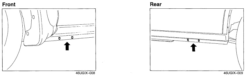
VEHICLE LIFT POSITIONS
DYNAMOMETER
When test-running a vehicle on a dynamometer
- Place a fan, preferably a vehicle-speed proportional type, in front of the vehicle.
- Connect an exhaust gas ventilation unit.
- Cool the exhaust pipes with a fan.
- Keep the area around the vehicle uncluttered.
- Watch the water temperature gauge.
COMPRESSED AIR
When using compressed air to clean or remove parts
- Wear protective eye wear.
- Hold a rag over the opening to prevent parts from shooting out.
- Take precautions so that people around you are not struck by flying
Conversion to SI Units (Systeme International d'Unites)
All numerical values in this manual are based on SI units. Numbers shown in conventional units are converted from these values.
Rounding off
Converted values are rounded off to the same number of places as the SI unit value. For example, if the SI unit value is 17.2 and the value after conversion is 37.84, the converted value will be rounded offto 37.8.
Upper and lower limits
When the data indicates upper and lower limits, the converted values are rounded down if the SI unit value is an upper limit and rounded up if the SI unit value is a lower limit. Therefore, converted values for the same SI unit value may differ after conversion. For example, consider 2.7 kgf/cm2 in the following specifications:
- 210-260 kPa {2.1-2.7 kgf/cm2, 30-38 psi}
- 270-310 kPa {2.7-3.2 kgf/cm2, 39-45 psi}
The actual converted values for 2.7 kgf/cm2 are 264 kPa and 38.4 psi. In the top specification, 2.7 is used as an upper limit, so its converted values are rounded down to 260 and 38. In the bottom specification, 2.7 is used as a lower limit, so its converted values are rounded up to 270 and 39.
SAE STANDARDS
In accordance with new regulations, SAE (Society of Automotive Engineers) standard names and abbreviations are now used in this manual. The table below lists the names and abbreviations that have been used in Mazda manuals up to now and their SAE equivalents.
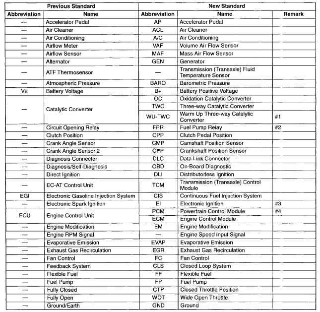
- Directly connected to the exhaust manifold
- In some models, there is a fuel pump relay that controls pump speed. That relay is now called the fuel pump relay (speed).
- Controlled by the ECM (PCM)
- Device that controls the engine and powertrain
FUNDAMENTAL PROCEDURES
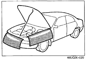
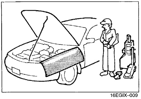
- PROTECTION OF THE VEHICLE
- Always be sure to cover fenders, seats, and floor areas before starting work.
- Always be sure to cover fenders, seats, and floor areas before starting work.
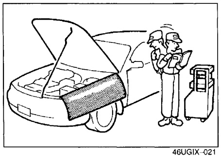
- PREPARATION OF TOOLS AND MEASURING EQUIPMENT
- Be sure that all necessary tools and measuring equipment are available before starting any work.
- Be sure that all necessary tools and measuring equipment are available before starting any work.
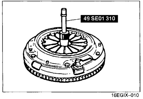
- SPECIAL TOOLS
- Use special tools when they are required.
- Use special tools when they are required.
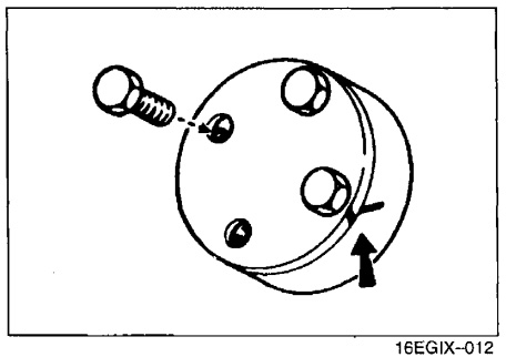
- REMOVAL OF PARTS
- While correcting a problem, try also to determine its cause. Begin work only after first learning which parts and subassemblies must be removed and disassembled for replacement or repair. After removing the part, plug all holes and ports to prevent foreign material from entering.
- While correcting a problem, try also to determine its cause. Begin work only after first learning which parts and subassemblies must be removed and disassembled for replacement or repair. After removing the part, plug all holes and ports to prevent foreign material from entering.
- DISASSEMBLY
- If the disassembly procedure is complex, requiring many parts to be disassembled, all parts should be disassembled in a way that will not affect their performance or external appearance and identified so that reassembly can be performed easily and efficiently.
- If the disassembly procedure is complex, requiring many parts to be disassembled, all parts should be disassembled in a way that will not affect their performance or external appearance and identified so that reassembly can be performed easily and efficiently.
- Inspection of parts
- When removed, each part should be carefully inspected for malfunctioning, deformation, damage, and other problems.
- When removed, each part should be carefully inspected for malfunctioning, deformation, damage, and other problems.
- Arrangement of parts
- All disassembled parts should be carefully arranged for reassembly. Be sure to separate or otherwise identify the parts to be replaced from those that will be reused.
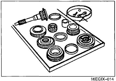
- All disassembled parts should be carefully arranged for reassembly. Be sure to separate or otherwise identify the parts to be replaced from those that will be reused.
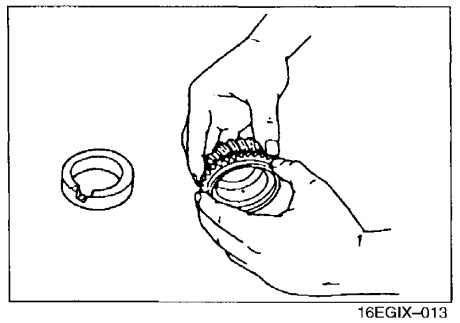
- Cleaning parts for reuse
- All parts to be reused should be carefully and thoroughly cleaned in the appropriate method.
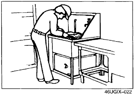
- Warning: Using compressed air can cause dirt and other particles to fly out, causing injury to the eyes. Wear protective eye wear whenever using compressed air. All parts to be reused should be carefully and thoroughly cleaned in the appropriate method.
- All parts to be reused should be carefully and thoroughly cleaned in the appropriate method.
REASSEMBLY
Standard values, such as torques and certain adjustments, must be strictly observed in the reassembly of all parts.
If removed, these parts should be replaced with new ones:
- Oil seals 2. Gaskets
- O-rings 4. Lock washers
- Cotter pins 6. Nylon nuts
Depending on location:
- Sealant should be applied to gaskets.
- Oil should be applied to the moving components of parts.
- Specified oil or grease should be applied at the prescribed locations (such as oil seals) before reassembly.
ELECTRICAL TROUBLESHOOTING TOOLS
TEST LIGHT
The test light, as shown in the figure, uses a 12V bulb. The two lead wires should be connected to probes.The test light is used for simple voltage checks andfor checking for short circuits.
JUMPER WIRE
A jumper wire is used to create a temporary circuit. Connect the jumper wire between the terminals of a circuit to bypass a switch.
VOLTMETER
The DC voltmeter is used to measure circuit voltage. A voltmeter with a range of 15V or more is used by connecting the positive (+) probe (red lead wire) to the point where voltage is to be measured and the negative (-) probe (black lead wire) to a body ground.
OHMMETER
The ohmmeter is used to measure the resistance between two points in a circuit, and to check for continuity and short circuits.
ELECTRICAL PARTS
BATTERY CABLE
Before disconnecting connectors or removing electrical parts, disconnect the negative battery cable.
CONNECTORS Data Link Connector
Insert the probe into the service hole when connecting a jumper wire to the data link connector.
Disconnecting Connectors
When disconnecting two connectors, grasp the connectors, not the wires. Connectors can be disconnected by pressing or pulling the lock lever as shown.
Locking connector
When locking connectors, listen for a click that will indicate they are securely locked.
ELECTRICAL PARTS
Inspection
- When a tester is used to check for continuity or to measure voltage, insert the tester probe from the wiring harness side.
- Check the terminals of waterproof connectors from the connector side, as they cannot be accessed from the wiring
- Caution: To prevent damage to the terminal, wrap a thin wire around the lead before inserting it into the terminal.
TERMINALS
Inspection
Pull lightly on individual wires to check that they are secured in the terminal.
Replacement
Use the appropriate tools to remove a terminal as shown. When installing a terminal, be sure to insert it until it locks securely. Insert a thin piece of metal from the terminal side of the connector, and then, with the terminal locking tab pressed down, pull the terminal out from the connector.
SENSORS, SWITCHES, AND RELAYS
Handle sensors, switches, and relays carefully. Do not drop them or strike them against other objects.
FUSE
Replacement
- When replacing a fuse, be sure to replace it with one of the specified capacity. If a fuse again fails after it has been replaced, the circuit probably has a short and the wiring should be checked.
- Be sure the negative battery terminal is disconnected before replacing a main fuse (120A).
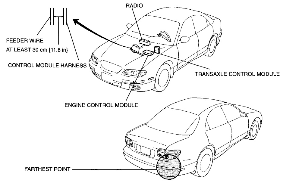
INSTALLATION OF RADIO SYSTEM
If a radio system is installed improperly or if a high-powered type is used, the CIS and other systems may be affected.
When the vehicle is to be equipped with a radio, observe the following precautions:
- Install the antenna at the farthest point from control modules.
- Install the antenna feeder as far as possible from the control module harnesses (at least 30 cm {11.8 in}).
- Ensure that the antenna and feeder are properly adjusted.
- Do not install a high-powered radio system.
AUDIO ANTITHEFT SYSTEM
An audio with an antitheft function is optionally available. Before removing the negative battery terminal or disconnecting the audio power source, obtain the code number and deactivate the audio antitheft system.