GT-R Model R32 Series Workshop manual
Nissan GT-R R32 Service repair manual
Foreword
This service manual has been prepared primarily for the purpose of assisting service personnel in providing effective service and maintenance of the GT-R. This manual includes procedures for maintenance, adjustments. removal and installation, disassembly and assembly of components, and trouble-shooting.
All information, illustrations and specifications contained in this manual are based on the latest product information available at the time of publication. If your car differs from the specifications contained in this manual. consult your NISSAN dealer for information.
The right is reserved to make changes to specifications and methods at any time without incurring any obligation to make or install similar changes on vehicles and/or parts previously purchased.
IMPORTANT SAFETY NOTICE
The proper performance of service is essential for both the safety of the mechanic and the efficient functioning of the vehicle. The service methods in this Service Manual are described in such a manner that the service may be performed safely and accurately. Service varies with the procedures used, the skills of the mechanic and the tools and parts available. Accordingly, anyone using service procedures, tools or parts which are not specifically recommended by NISSAN must first completely satisfy themselves that neither their safety nor the vehicle's safety will be jeopardized by the service method selected.
HOW TO USE THIS MANUAL
Preparation Operation Explanation
This manual describes important items for installation, removal, assembly, disassembly, inspection and repair. CAUTION: A general description of a visual inspection and cleaning of disassembled parts has generally been omitted. However, when the parts will be used again, make sure to perform visual inspection and cleaning as necessary.
Configuration Components, Operation Contents and Procedures
The configuration components and operation contents and procedures are shown after the title of the operation. The preparation standards and important operation points such as parts which cannot be used again, tightening torque and lubrication locations are also indicated.
CONFIGURATION COMPONENTS AND OPERATION CONTENTS
The necessary operations for installation, removal, assembly and disassembly are indicated by the part (part name). This description is used if the only ideal procedure cannot be determined or there are many types of components. [Point] is used to indicate operation procedures which are necessary.
Example: Front accelerator assembly and disassembly
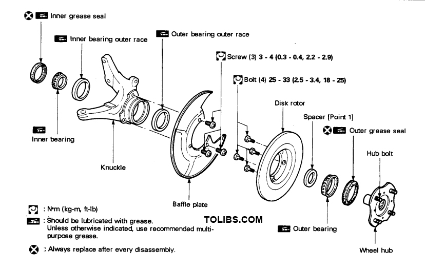
STRUCTURAL PARTS DIAGRAM AND OPERATIONAL SEQUENCE
The names of the parts required for removal and replacement and assembly and disassembly opera tions are shown. The operational sequence must be performed in the sequence of the indicated num bers. Assembly is the reverse of disassembly except when otherwise indicated.
Example: Light combination switch ASSY installation and removal
OPERATION NAME SYMBOLS
(Removal) (Installation) (Additional work required)
- (Removal): Indicates an operation (preparation, inspection adjustment, etc.) that is only necessary for removal.
- (Installation): Indicates an operation (preparation, inspection adjustment, etc.) that is only necessary for installation.
- (Removal) (Installation): Indicates an operation (preparation, inspection adjustment, etc.) that is only necessary for both removal and installation.
- (Additional work required): Indicates a supplementary operation (removal, installation, etc.) to be performed before the operation indicated in the section title.
Fast, Accurate Operations
- Check the vehicle damage carefully, make a careful diagnosis of the damage and perform the correct operation systematically.
- Check the correct part assembly condition before removal or disassembly. Make alignment marks when necessary in locations which will not interfere with the part functions.
- Replace oil seals, gaskets, packings, O-rings, locking washers, cotter pins, self-locking nuts, etc. with new ones. These items are indicated, "Always replace after every disassembly." and must be replaced with a new part.
- Before servicing the vehicle, protect fenders, upholstery and carpeting with appropriate covers. Be careful so that keys, buckles or buttons on your person do not scratch the paint.
- Refer to the lubrication section and only use the lubricants which are described.
- When replacing parts always use genuine Nissan replacement parts.
- Verify the inspection circuit in a wiring figure before performing any inspection with a circuit tester.
- An inspection may be difficult with a normal test probe when a connector pin is extremely small. If this occurs, wind a small pin or wire around the test probe, or sharpen the end of the probe to perform the inspection.
Safety PRECAUTIONS
- The RB26DETT engine exhaust valves contain metallic sodium. Be careful when using or discarding the valves. (Refer to section B3, 80, Cylinder Head Removal and Installation.)
- Do not operate the engine for an extended period of time without proper exhaust ventilation. Keep the work area well ventilated and free of any inflammable materials. Special care should be taken when handling any inflammable or poisonous materials, such as gasoline, refrigerant gas, etc. When working in a pit or other enclosed space, be sure to properly ventilate the area before work- ing with hazardous materials. Do not smoke while working on any vehicle.
- Before jacking up the vehicle, use wheel chocks or tire blocks on the wheels to prevent the vehicle from moving. After jacking up the vehicle, support the vehicle weight with safety stands at the points designated for proper lifting and towing before working on the vehicle. These operations should be done on a level surface.
- When the automobile is lifted on a rigid rack, it should be supported in fixed locations.
- Before starting removal and installation of the electrical system or other repairs which do not require battery power, always turn off the ignition switch, then disconnect the ground cable from the battery to prevent accidental short circuits.
Electronic Trouble Diagnosis System
- Use measurement equipment such as the CONSULT electronic system diagnosis tester and an oscilloscope to perform diagnosis operations efficiently.
- The CONSULT unit is a hand-held compact type of tester. It transmits signals to the vehicle loading control units when the diagnosis connector is connected and can perform all types of diagnosis and testing.