1958 Ford Tractor 801-D, 901-D Owner’s Manual
Ford 801-D, 901-D 1958 Owner’s Manual Supplement
FOREWORD
Your new Ford Diesel Tractor is basically the same (except for the power source) ns the Ford gasoline tractors. The information in this manual covers only the portions of your tractor differing from the gasoline model and is provided as a supplement to the regular Owner’s Manual included with your tractor. For complete operation and maintenance instructions on your Ford Diesel Tractor, trier to both the Owner's Manual and this supplement.
THE DIESEL TRACTOR
GENERAL INFORMATION
The difference between the diesel and gasoline tractor lies mainly in the method of fuel supply and subsequent fuel ignition. Over the last twenty years, the diesel engine has been widely used in heavy commercial vehicles and tractors. However, it is only now coming into service in the lighter types of vehicles and tractors.
FOUR STROKE CYCLE
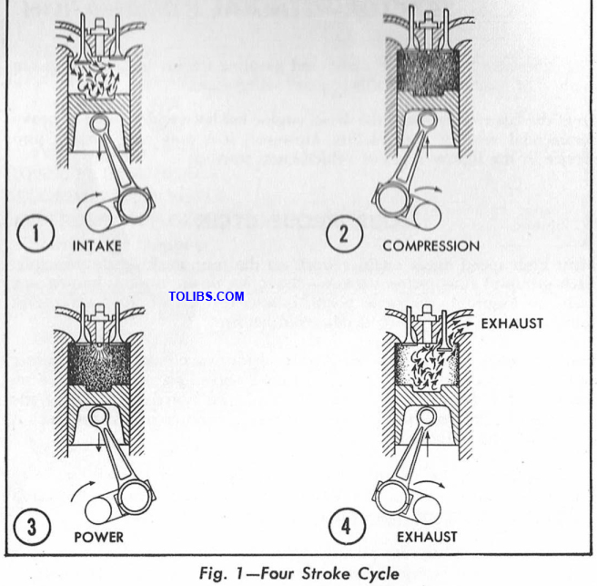
Most high speed diesel engines work on the four stroke cycle principle. Each group of four piston strokes-down, up, down, up- is known as a cycle. In Figure 1, the same piston is seen in each of the four strokes completing the cycle which is described below.
- Intake Stroke: During this stroke, the piston travels down the cylinder and draws in air through the open intake valve. The exhaust valve remains closed during this stroke. It should be noted that, unlike the gasoline engine, only filtered air and not a mixture of air and fuel is drawn into the cylinder.
- Compression Stroke: Both valves are closed during this stroke when the piston comes up and compresses the air. The action of the piston in compressing the air raises the temperature and pressure.
- Power Stroke: When the piston approaches the top of the cylinder, a fine spray of fuel is injected into the cylinder by means of the injection pump and injector. The increased pressure of the air and the resulting high temperature causes the finely atomized fuel to ignite. Both valves being closed, the pressure of the expanding gases forces the piston down the cylinder.
- Exhaust Stroke: The cycle is completed on the exhaust stroke. The piston moves up and expels the burned gases through the open exhaust valve. The intake valve remains closed throughout this stroke.
COMPRESSION RATIO
The fuel injected into the diesel engine cylinder, in the form of a fine spray, is ignited solely by the high temperature of the air charge within the cylinder. To obtain this high temperature, it is necessary to employ a high compression ratio. This means simply that the total volume of air drawn into the cylinder during the intake stroke has to be compressed into a very small volume when the piston reaches the top of its stroke.
The ratio of these two volumes in the Ford Diesel engine is 16 to 1. For comparison, the Ford gasoline engine compression ratio is 7.5 to 1. Remember, however, that the fuel in the gasoline engine is ignited not by the heat generated during the compression stroke, but by an electrical spark.
These higher compression ratios and their resulting high working pressures necessitate using parts which are stronger than those used in a gasoline engine.
FUEL SUPPLY
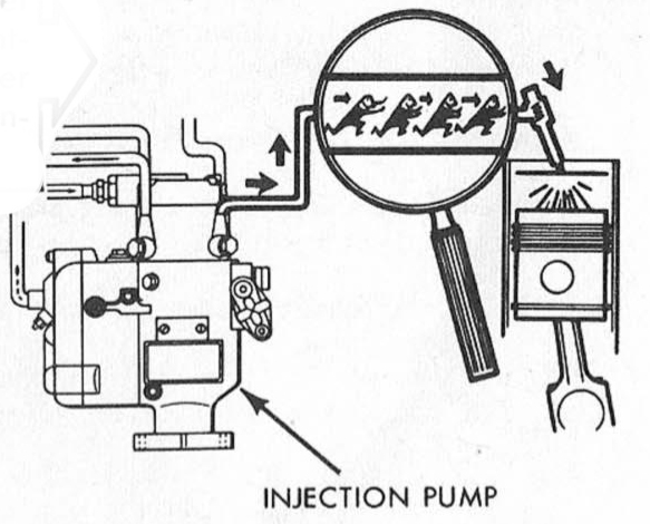
The fuel supply to the combustion chamber is controlled by an injection pump. This pump meters and distributes the fuel under pressure to the individual injectors, which in turn spray (atomize) the fuel into each combustion chamber.
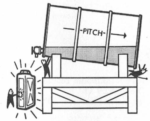
Install your storage container above the ground and tilt the tank so the discharge outlet is on the highest end of the tank. Provide a drain plug at the lowest point of the tank so that moisture and sediment can be drained off periodically. Install a suitable filter on the discharge outlet of the storage container.
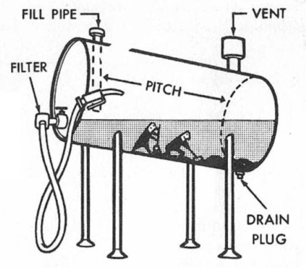
A 50 gallon drum makes a JJ suitable container for diesel fuel, provided that it is tilted on the stand. The drum should XI be cleaned and flushed before each refilling.
The volume of fuel supplied to the engine is controlled by a metering device within the pump which is activated by the governor mechanism. The high pressure required to operate the injectors is created by internal mechanisms within the pump and the distribution of the fuel to each injector in the proper firing order is controlled by the relationship of the various passages within the pump. The injection pump is driven by the engine camshaft.
DIESEL FUEL STORAGE
The tolerances of the closely fitted injector components and fuel injection pump parts are held within millionths of an inch, so it is vitally important that they be kept free from the damaging action of minute particles of dirt that may enter the fuel-particularly during fuel handling or storage. See Figure 2.
Proper handling and storage of diesel fuels can help you to avoid costly repair bills on the fuel injection system of your tractor.
- Store diesel fuel in black iron tanks or containers. Galvanized tanks should never be used.
- Let the fuel settle at least 12 hours before use. This will permit any sediment or water in the fuel to settle to the bottom of the container. Use the largest container possible for the storage of fuel and keep the container as full as possible to avoid condensation
If you are not using a filter on your storage tank, it is recommended that a funnel equipped with a 100 mesh wire screen be employed when filling your tractor fuel tank. A chamois skin will do the job if a mesh screen funnel is not available.
PLEASE NOTE: The micronic filter fitted in the fuel line of your tractor serves to remove occasional foreign material in the fuel,, but it will not be sufficient to handle the volume of dirt caused by improper storage and handling. Change this filter every 400 hours or at least every 6 months.
RECOMMENDED FUELS
Use Diesel Fuel Oil No. 2 (No. 2D) with a minimum cetane rating of 45 at temperatures above 20° F. Use Diesel Fuel Oil No. 1 (No. ID) with a minimum cetane rating of 50 at temperatures below 20° F.
CONTROLS AND OPERATION
STARTING AND STOPPING THE DIESEL ENGINE
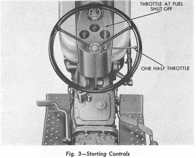
Throttle Control: The hand operated throttle control lever is located at the right side of the steering wheel column. From the off position, (dotted line, Figure 3) which closes the fuel supply at the pump, the throttle should be pulled down to half open position when starting. Turn the starter switch on (clockwise) and put the gear shift lever in neutral position. Press the starter button to start the engine.
The Starter Switch: The starter switch controls the electrical circuit powered by a 12-volt battery. The primary purpose of this circuit is to start the engine. Once the engine is running, it no longer requires the electrical circuit and it cannot be stopped by cutting off the starter switch. To stop the engine, the throttle must be pushed all the way up beyond the idle stop as shown in Figure 3, cutting off the fuel supply at the pump. During operation of the tractor, the starter switch is left on to complete the circuit to the generator warning light on the instrument panel. This generator warning light also serves as a warning for the operator to turn off the starter switch after the fuel supply has been cut off by the throttle lever, stopping the engine.
COLD WEATHER STARTING-DIESEL TRACTOR ACCESSORIES
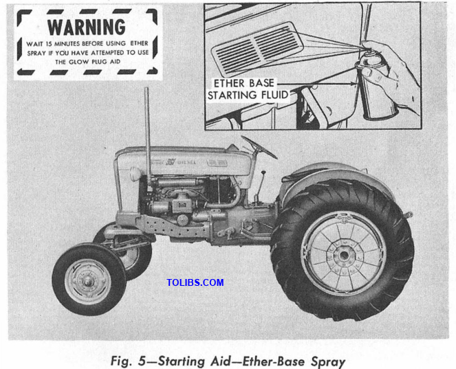
Glow Plug kits are available for use on the diesel tractor to facilitate cold weather starting. For winter weather, above 15° F. the Glow Plug aid will normally be sufficient to start the engine. For cold weather starting, below 15° F., it is recommended that an ether base starting fluid in spray-type containers be sprayed into the air intake louvre. (Complete instructions are given on the container.) This starting fluid is available at your local Ford Tractor and Implement Dealer or from diesel fuel suppliers.
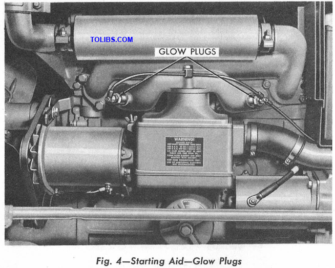
Glow Plugs: Glow Plugs, Figure 4, installed in the air intake manifold, heat the air before it enters the combustion chamber. The push button switch, controlling the electric current to these heating elements, is mounted above the starter key. Turn the starter switch on and pull the throttle down to throttle from idle. Depress the Glow Plug circuit button for approximately 30 to 60 seconds, depending on the temperature, before starting the engine. Use the starter button and continue to depress the Glow Plug Button to start the tractor after initial heating of the air.
MAINTENANCE
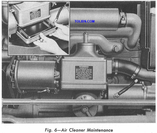
Service daily or every ten hours. The air cleaner assembly is of the oil bath type and functions in the same manner as those used on Ford gasoline tractors. The assembly is attached directly to the intake manifold and receives its air supply via an inlet tube, which is connected to the pre-cleaner screen and louvred cover assembly on the left side hood panel. See Figure 6.
Air Cleaner Removal:
- Loosen two hose clamps at the air inlet tube to air cleaner connection.
- Remove the oil bath tray from the air cleaner housing.
- Remove the air cleaner and gasket from the intake manifold. (2 bolts and lockwashers)
Air Cleaner Service:
- Empty the oil bath tray and clean the tray thoroughly. Fill to the oil level mark (one pint) with engine crankcase oil.
- Immerse the air cleaner assembly in clean diesel fuel, flush and drain thoroughly.
- CAUTION: DO NOT USE ANY OIL IN THE CUP OTHER THAN SPECIFIED. LIGHT WEIGHT ENGINE OILS CAN BE SUCKED INTO THE FIRING CHAMBERS AND CAUSE A RUN-AWAY ENGINE.
Air Cleaner Installation:
- Install the air cleaner on the intake manifold.
- Assemble the oil bath tray to the air cleaner.
- Attach the air inlet tube to the assembly at the hose connection and tighten the clamps.
Service every 100 hours
Engine Crankcase: Change the engine oil in your new tractor at the 50 hour inspection and every 100 hours of operation thereafter. Drain the oil after the engine has reached normal operating temperature. Refill the crankcase with four quarts of good heavy duty or premium engine oil that is intended for use in diesel engines only and add one extra quart of oil if the filter cartridge is replaced.
Recommended engine oils:
- SAE 30* DM or supplement one (SI )-Temperatures above 55° F.
- SAE 20-20W DM or supplement one (SI)-Temperatures 20° F. to 55° F.
- SAE 10-10W* DM or supplement one (SI )-Temperatures below 20° F.
NOTE: Multi-viscosity oils and oils marked ML, MM or MS are not recommended.
Service every 400 hours or every 6 months
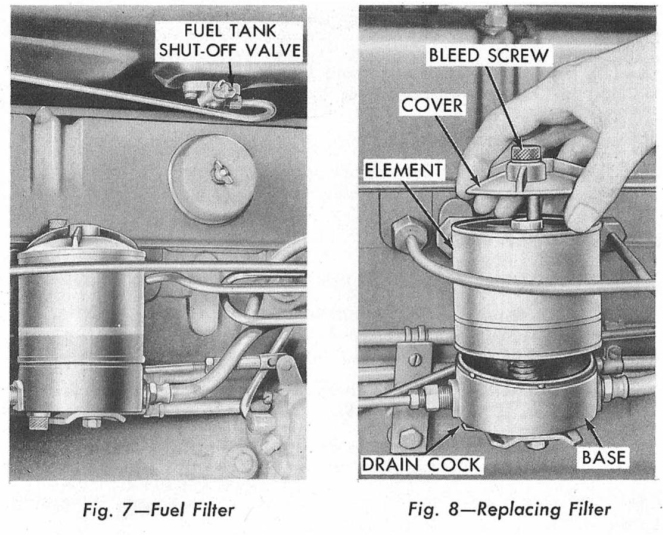
Fuel Filter Replacement:
- Close the fuel shut-off valve located at the bottom center of the tank, Figure 7.
- Open the drain cock at the bottom rear of the filter base, Figure 7, and drain the fuel into a drain pan.
- Remove the cover assembly and filter element by turning the cover counterclockwise. (See Figure 8).
- NOTE: The filter element is spring loaded and will raise from the filter base as the cover assembly is backed off. There are tivo filter element cork gaskets located one at the top and one at the bottom of the element. The gaskets and element should be discarded.
- Remove the rubber grommet and spring from the center post in the filter base.
Wipe out inside of the filter base with a clean rag and flush with clean diesel fuel allowing the fuel to drain through the drain cock. Clean the cover and bolt assembly plus the base spring in diesel fuel, and install the filter element as follows:
- Assemble the spring and the rubber grommet on the center post of the filter base.
- Use new gaskets at the top and bottom of the new filter element and position the element over the rubber grommet on the center post of the filter base.
- Place the cover and bolt assembly through the center core of the element and depress the element slightly to start the bolt threads. Tighten the cover and bolt assembly, finger tight.
Bleeding the Fuel Filter:
- Open the tank fuel shut-off valve at the bottom center of the tank.
- Open the drain cock at the bottom rear of the fuel filter base. The fuel will flow by gravity from the tank to the filter. Close the drain cock in the filter base when fuel flows through.
- Open the air bleed screw located at the top of the filter assembly. Two turns of the screw is sufficient to release trapped air.
- Observe the fuel leaking past the screw and when the air bubbles disappear, close the bleed screw.
CAUTION: Never open the bleed screw when the engine is running as air will be sucked into the system.
Fuel Injectors: Fuel injectors should be removed, cleaned and tested after every 400 hours of operation. THIS IS VERY IMPORTANT. To prevent waste of useful tractor power, we suggest that you contact your Ford Tractor and Implement Dealer when the fuel injectors on your tractor have 400 hours of operating time. Your Ford Tractor and Implement Dealer has access to the special testing and adjusting equipment required for servicing diesel tractor injection systems. See Figure 9.
Thermostat: The thermostat automatically regulates the temperature within the cooling system by controlling the flow of coolant through the radiator. The thermostat starts to open at 177-182 degrees and is fully open at 197-202 degrees.
FUEL SYSTEM ADJUSTMENTS
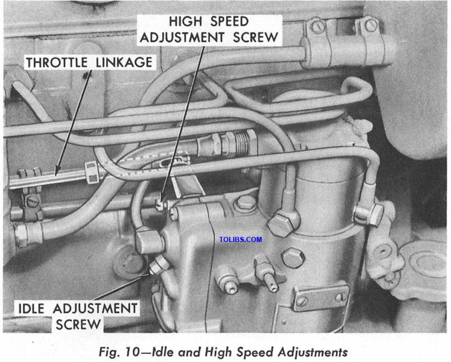
IDLE AND HIGH SPEED ADJUSTMENTS
The fuel injection pump is provided with an engine idle adjusting screw and high speed adjusting screw shown in Figure 10. In addition, the throttle linkage may be adjusted to provide for the correct amount of dead travel for the hand throttle lever. Each of these adjustments is important to the operating efficiency of the Ford Diesel Tractor and should be checked whenever the tractor is serviced.
With clean injectors and normal fuel pressure (2700 pounds per square inch) only a small percentage of your tractor engine’s power is required to operate the fuel injection pump.
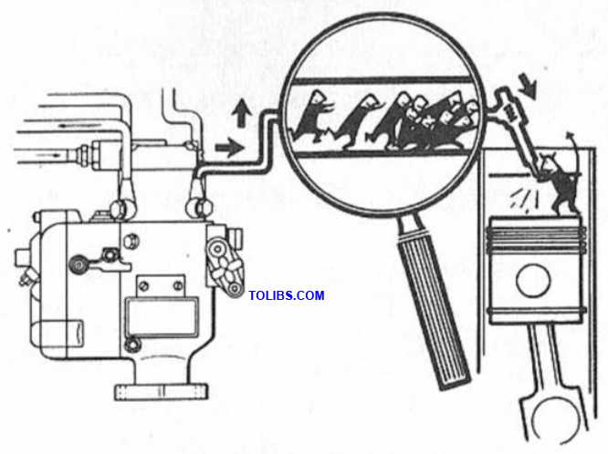
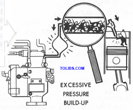
Dirty or improperly adjusted fuel injectors can contribute to a fuel pressure build-up as high as 7500 pounds per square inch in the injection lines requiring an increased amount of the engine power to drive the injection pump.
This means loss of injector efficiency and loss of engine power! Power and efficiency that could be utilized for useful work. Greater fuel consumption and the possibility of worn or broken parts occur due to the additional load exerted on the pump.
Idle Speed Adjustment:
- Start and warm up the engine to the normal operating temperature of 180°.
- Position the hand throttle lever for idle.
- Adjust idle speed to 600 RPM as follows:
- Back off the jam nut on the pump idle speed adjusting screw and use an alien wrench to turn the screw.
- Turn the screw in to increase engine RPM and out to decrease engine RPM.
- Lock the screw in position after the correct idle speed has been obtained.
Throttle Linkage Adjustment: The linkage should be checked for proper length in relation to the hand throttle lever dead travel at the idle position when making normal service adjustments for engine speed.
- With the engine running, set the hand throttle lever to the idle stop and disconnect the throttle linkage at the injection pump operating lever.
- Rotate the pump operating lever rearward to its idle position.
- NOTE: There is no idle stop on the pump operating lever. When it is at idle position, a.slight drag will be felt.When the lever is moved further to override this drag, it contacts the stop and shuts off the fuel.
- With the pump operating lever in idle position, adjust the throttle linkage by loosening the lock nut and by turning the ball cage until it aligns with the ball on the pump operating lever. Reconnect the linkage.
- Check for idle speed of 600 RPM with the hand throttle lever against the idle stop. Adjust the idle speed setting at the pump if a correction is required. See "Idle Speed Adjustment.”
- Move the hand throttle lever off of its stop, about % to (measured at the hand throttle lever). The engine should just start to pick up speed at this position, which insures a small amount of dead travel in the hand lever throttle before the engine accelerates.
- Repeat the linkage adjustment until the hand throttle lever dead travel is established.
- NOTE: The dead travel is entirely controlled by the length of the throttle linkage and must be obtained to prevent activating of the pump governor in low idle range.
High Speed Adjustment:
- With the engine running at normal operating temperature, set the hand throttle lever at full throttle. The Proof-Meter reading should be 2430 RPM with five-speed transmission tractors, or 2230 RPM with four-speed transmission tractors (no load).
- Adjust for the proper maximum no load speed as follows:
- Loosen the jam nut on the pump operating lever stop screw.
- Use a screwdriver and turn the screw "out” to increase engine RPM. Turn the screw "in” to decrease engine RPM.
- Lock the screw in position with the jam nut after the proper adjustments have been made.
Checking For Correct Pump to Engine Timing
- Remove the timing window cover and gasket on the fu wiresjfction pump and rotate the engine until the timing marks align shown in Figure 11.
- Remove the engine flywheeel timing cover and check the flywheel degree marking which should read 18° BTDC. If it does not, rotate the flywheel by engaging a screwdriver in the ring gear and adjust for 18° BTDC.
ELECTRICAL SYSTEM
The 12-volt electrical system of the Ford Diesel Tractor, as compared to the 6-volt system of the Ford Gasoline Tractor, doubles the available voltage and doubles the power of the electrical supply system.