Ford Bus 450 Owners Manual

Bus Owner's Manual Ford Chassis 450/550 Series
Congratulations, and thank you for purchasing a Krystal Enterprises Vehicle
You have taken ownership of a true luxury vehicle which is in a class all its own. We are providing this manual to familiarize you with your new Krystal Enterprises Professional Bus. This manual shall serve as a reference document for the operations and maintenance procedures that shall be required throughout the life of your vehicle. This edition covers all our Ford Chassis models, and is designed to be used in conjunction with the original chassis manufacturer’s owner’s literature, as well as all other component manufacturers literature.
IMPORTANT: PLEASE READ CAREFULLY
For your safety and the safety of others, we ask that you completely familiarize yourself with this manual, and all other operators manuals before you operate this vehicle for the first time.
ATTENTION
WHEN OPERATING A VEHICLE WITH A VAPOR DOUBLE PANEL AIR OR ELECTRIC ACTUATED PASSENGER ENTRANCE DOORS, THE FOLLOWING PRECAUTIONS SHOULD BE TAKEN.
AIR DOORS
The E mergency Release Valve System-(must be checked on a daily basis) Once the emergency release valve has been actuated (by turning the red handle counter clockwise), it should be possible to open the doors by pushing outward with your hand after about 5 seconds.
The Obstruction Sensing System (Sensitive Edge)-(must be checked on a daily basis)Only when the door is closing, can reversing be actuated. The reversing motion should be shut off at about 10 to 30 mm before the fi nal closing position. If the reversing process actuates too late, the sensitivity of the differential pressure switch should be adjusted again. Call the KRYSTAL SERVICE DEPT.
ELECTRIC DOORS
The Emergency Release Lever System-(must be checked on a daily basis) Once the emergency release lever has been actuated (by pushing the red handle from right to left as indicated on the sticker), it should then be possible to open the doors by pushing the panels outward with your hand.
Pre-Trip Inspection
- Is each securement station properly equipped with four securement straps, a lap belt, and a shoulder belt?
- Are all straps and belts in good working condition? Any defects such as cut, frayed, contaminated or damaged webbing, improperly functioning buckles or hardware, or broken or worn parts, require replacement of the entire strap or belt assembly.
- Are all floor anchorages, (i.e., tracks or plates), clear of dirt or debris to allow for proper system fi ttingattachment?
- Is there a clean, dry container in the vehicle to allow for storage of the system when not in use?
- Is the vehicle equipped with a web/belt cutter for use in the event of an emergency evacuation?
- Are complete system operational instructions, in either printed or decal form, located within the vehicle compartment to serve as a reference?
CAUTION: Never utilize the Occupant Restraint System unless you are fully trained, if you’re not sure what to do, always call your Kinedyne Representative for Assistance!
Emergency Roof Hatch Exit
This is a Dual Purpose hatch used for Emergency Egress and Ventilation purposes.
SUGGESTED MAINTENANCE
Periodically inspect attaching fasteners for evidence of loosening due to tampering, and regularly clean surface with a mild soap and water.
CAUTION: When removing graffi ti, it is the customers responsibility to ensure cleaning solutions are compatible with the materials used on Safety Vents. Solutions containing, acetone, ether, lacquer thinner, or other solvents can destroy the high strength properties of many engineering plastics - AVOID these cleaners.
Quick Reference Guide
BCP (Battery Charge Protection Mode) Note: This system has been set-up for Automatic Battery Charge Protection, which becomes active whenever the following enabling conditions are met:
ENABLING CONDITION:
- Vehicle NOT moving (speed=0 MPH).
- Service Brake NOT pressed.
- Vehicle Transmission Range in Park/Clutch NOT pressed.
- RPM's inside of safe operating range.
- Transmission Fluid Temperature below 240˚ F.
- Engine Coolant Temperature below 230˚ F.
- Brake Lights Functional
- Foot Off Accelerator Pedal
AUTOMATIC BATTERY CHARGE PROTECTION
Any time your vehicle is Powered-up”, Charge Protection is automatically engaged, THIS FUNCTION SHOULD NOT NORMALLY BE DISABLED.
- Charge Protection will remain in effect until which time, any of the above stated ENABLING CONDITIONS are no longer met, or until you manually dis-engage the BCP button on the DRIVERS OVERHEAD CONTROL PANEL, see photo at right.
TO DEACTIVATE “AUTOMATIC BATTERY CHARGE PROTECTION” OR “FAST IDLE” Do the following:
- Press the Manual Engage button on the DRIVERS OVERHEAD CONTROL PANEL and release.
- To exit “AUTOMATIC CHARGE PROTECTION Mode”, simply depress the service brake pedal. See the Off Road Engineering literature for specifi c details regarding other operating parameters.
Basic Operating Instruction Bulkhead mounted TV and DVD
For specific detailed information see Manufacturers DVD Operating Instructions.
- Turn on the TV using the power on the TV or the button on the remote (Note: TV must be set to Video #1 for DVD to work)
- To view video, push the TV/Video button to switch between TV and DVD(Video).
- To view tapes select VCP, then press the DVD power button on the remote.
- The DVD buttons on the remote will now Operate all the functions of the DVD
Back-Up Ca Operation
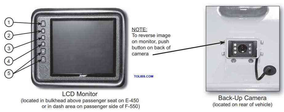
Monitor Controls
- Power Button, glows dimly when system is connected fully manual, becoming bright upon activation
- A/B input Select Button, toggles active display between AV1 and AV2 inputs
- Day/Night Mode Button, toggles intensity of LCD screen for day or night operation, (day=maximum intensity, night=less intensity)
- Picture Adjustment Menu Button, accesses on-screen-display, to adjust (brightness, contrast, color, tint). Use the Volume control to adjust each up or down, as indicate by a bar graph at bottom on screen.
- Volume Button, controls +- output volume of built-in speaker, when feature is connected. Also used in Picture Adjustment Mode.
System Operation
This system consists of two major components:
1. The Back-Up Camera 2. LCD Monitor
The system may be connected two ways:
- Fully manual, requiring the power button on the LCD Monitor to be pushed to energize the system and activate the monitor.
- Automatic, which activates the monitor whenever the ignition is turned to accessory or the engine is started.
For the double rear step (shown above) and the single rear step, operation is the same. The schematic (this page) explains the electrical operation of both steps. The power switch allows you to enable or disable step operation. When the step is enabled, opening the rear door automatically extends the step.
Note: See Manufacturers literature regarding periodic lubrication requirements.
Cargo Door Micro Switch
The switch is located at the rear cargo door upper hinge, shown at left and above. It operates the rear interior lights and also activates the door-ajar light on the front overhead control panel. This switch works in conjunction with the rear step, allowing the power switch (shown on previous page) to enable or disable step operation.
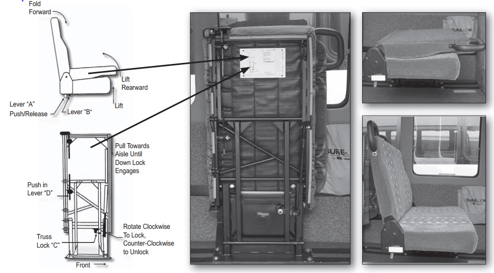
To Lower
- Rotate the Truss Lock “C” to unlock the assembly, then push Lever “D” and pull the top of the seat toward the aisle until it is locked in the down position.
- Push lever “A” forward, and lift the back cushion until the lever “A” has snapped back into the locked position.
To Raise
- Push lever “A” forward, and fold the back cushion down against the seat cushion until lever has snapped back into locked position.
- Push lever “B” upward, and lift the seat into the fold away position, and rotate the Truss Lock “C” to lock the assembly in place.
Bus Passeng g or Adding
Bus seating is mounted into the fl oor of the vehicle as shown in the photo.
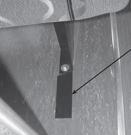
To move or add seating:
- Remove the black plastic track cover, so the track is exposed.
- Next remove the nut from the base.
NOTE: Nut must be perpendicular to the track when the seat is re-attached to the seat track.
Stainliners
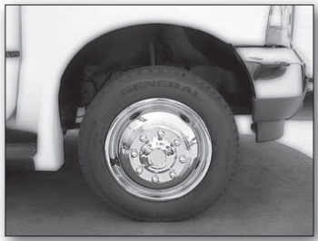
CAUTION: Wheel liners should only be removed using the Wheel Liner Tool provided with your vehicle. Damage could occur if the supplied tool is not used.
Wheel Liner Tool
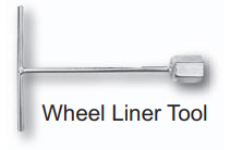
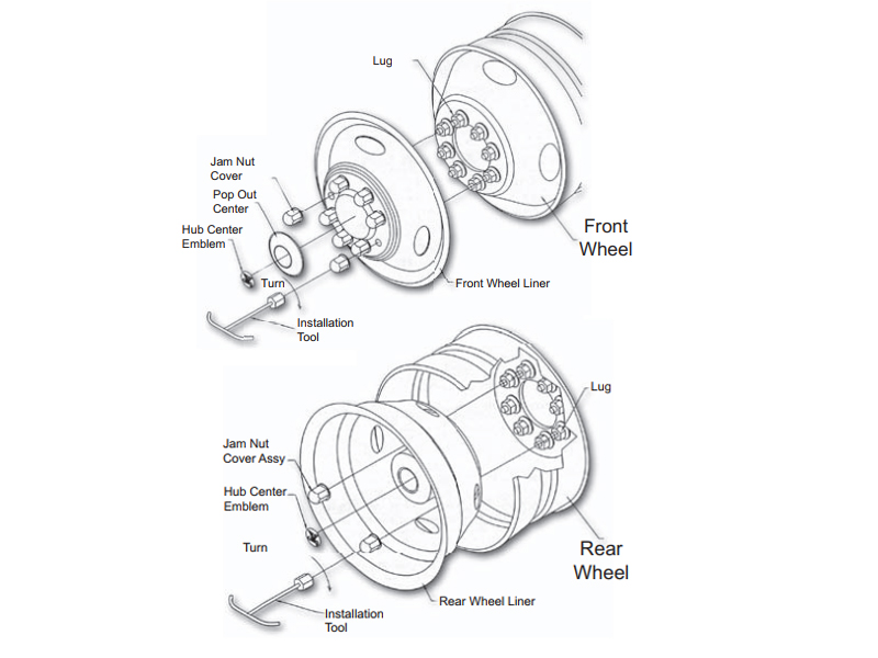
INSTALLATION - REMOVAL INSTRUCTIONS
NOTE: When removing or installing, never remove the original equipment lug nuts.
- TO REMOVE, simply place the Wheel Liner Tool over the Jam Nut Covers.
- Remove Jam Nut Covers from each wheel and remove Liners
- TO INSTALL, determine the correct placement of liners for proper hand hole alignment.
- Install Liner over studs, then install Jam Nut Covers w/built-in jam nuts onto the studs. Using the Wheel Liner Tool, tighten all Jam Nuts
The Obstruction Sensing System (Sensitive Edge) - (must be checked on a daily basis) Only when the door is closing, can reversing be actuated. The reversing motion should be shut off about 10 to 30 mm before the fi nal closing position. If the reversing process actuates too late, the sensitivity of the differential pressure switch would require re-adjustment.