Owner’s Manual Ford Tractor1957 601 / 801 Series
OPERATING THE HYDRAULIC SYSTEM
One of the outstanding features of your new Ford Tractor is the Live Action Hydraulic System. By simply moving the Touch Control Lever, the system provides instant hydraulic power for raising a wide variety of implements. Regardless of whether the clutch pedal is up or down, or whether the P.T.O.is engaged or disengaged, the system will respond smoothly, enabling you to adjust implements in fractions of an inch. The system incorporates two types of hydraulic control. Depending upon the type of implement used and the soil conditions and terrain encountered, the system may be operated in Implement Position Control or in Constant Draft Control.
Implement Position Control: To operate the hydraulic system in Implement Position Control, move the selector lever at the side of the tractor seat into the "UP” position (see Figure 12), and set the implement at the desired depth by moving the Touch Control Lever down. Where the ground is relatively level, the position control will keep the implement at the desired depth, even though the soil texture may vary. By setting the adjustable stop on the quadrant, the implement can always be returned to the original depth by moving the Touch Control Lever down to the stop.
Constant Draft Control: With the selector lever in the "DOWN” position, as shown in Figure 12, the hydraulic system is operating in Constant Draft Control. When an implement is lowered to work at a certain depth, the draft control will maintain the same draft, even though the ground contour or soil texture may change. If the draft increases, the hydraulic system will respond by raising the implement to decrease the draft. At the same time, the weight will shift to the tractor rear wheels, increasing traction until the implement has been automatically repositioned and the draft is decreased. When necessary, the operator may use the Touch Control Lever to make small adjustments in the system.
Hydraulic Picton Pump: Your new Ford Tractor is equipped with a piston-type hydraulic pump which provides a constant flow of oil to the Ford Tractor "live action” hydraulic system. For maximum efficiency and long pump life, always use the recommended hydraulic fluid and clean containers when filling the tractor hydraulic reservoir. When service on the hydraulic system becomes necessary, see your local Ford Tractor and Implement Dealer. He is properly equipped to meet your service needs.
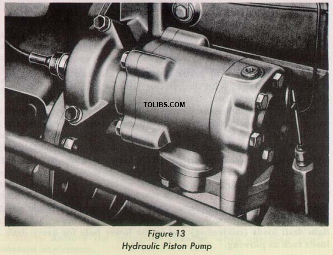
Figure 13. Hydraulic Piston Pump
ATTACHING IMPLEMENTS
Most implements can be easily and quickly attached to the tractor three point linkage. With the selector lever in Implement Position Control, back the tractor so that the lift links are directly above the cross shaft of the implement. Lower the links with the Touch Control Lever, until the sockets are aligned with the ends of the shaft. Attach the left link to the shaft and secure with the linch pin provided, then adjust the right link with the leveling crank (see Figure 14) and attach it in the same manner. Attach the adjustable top link to the implement and secure it with the linch pin.
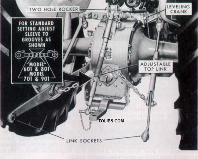
Figure 14 Leveling Crank and Adjustable Top Link
Two Hole Hydraulic Lift Rocker: The two hole hydraulic lift rocker on the Ford Tractor provides better control of sensitivity for light and heavy draft implements. Attach the top link in the upper hole for light draft loads (cultivating) and in the lower hole for heavy draft loads such as plowing.
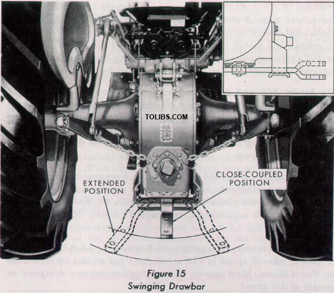
Figure 15 Swinging Drawbar
Adjustable Top Link: The fully adjustable top link provides improved implement performance and operation. The link may be adjusted to suit implement operation requirements by releasing the lock and rotating the sleeve until the desired length is obtained. The standard length of 2 5 inches is obtained by adjusting the link as shown on a decal located on the sleeve. (See insert, Figure 14.)
SWINGING DRAWBAR:
The swinging drawbar on your Ford Tractor, permits quick, easy attachment of pull type implements. The tractor can be operated with the swinging drawbar in either the "close-coupled” or "extended” positions (see Figure 15), and with the offset up or down (see insert, Figure 15). The drawbar may also be set and used in different positions either to the left or right of center (seven in all). When operating with P.T.O. driven equipment, the drawbar should always be in the "extended” position, with offset down.
CAUTION: Remove the Swinging Drawbar when attaching close mounted implements.
POWER TAKE-OFF OPERATION
The power take-off transfers engine power directly to mounted or drawn implements, or to belt driven equipment when a pulley is used. To operate the power take-off shaft, disengage the clutch and move the P.T.O. lever toward the rear of the tractor (see Figure 4). Once engaged, operation of the shaft is controlled by the tractor clutch. The Model 661 and 861 Ford Tractors are equipped with a live PTO clutch. To stop the forward motion of the tractor when operating with PTO driven equipment, depress the clutch pedal about half way as shown in Figure 16. To stop both the forward motion of the tractor and the operation of the implement, depress the clutch pedal all the way, as shown.
When desired, the live PTO clutch may be disengaged and the pedal set for normal, single clutch operation by repositioning the pin in the front hole of the clevis as shown in Figure 16. For further information on clutch adjustments, see page 48 under MECHANICAL MAINTENANCE.
The American Society of Agricultural Engineers (A.S.A.E.) standard for power take-off speed is 540 revolutions per minute as shown on the Proof-Meter. Most power take-off implements are designed to operate at this speed.
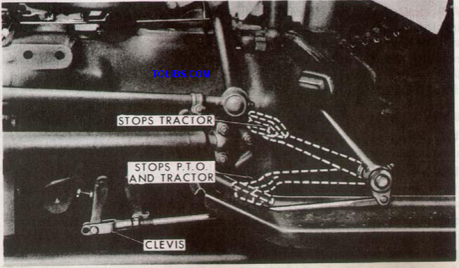
Figure 16 Operating the Live PTO Clutch
Power Take-Off Shaft: Your Ford Tractor is equipped with a standard P.T.O. shaft (!%" diameter) in accordance with A.S.A.E. specifications. When attaching P.T.O. driven equipment (built to A.S.A.E. standards) to your Ford Tractor, it is not necessary to use special adaptors or extensions. However, a P.T.O. shield is available as extra equipment from your Ford Tractor and Implement Dealer. This shield should be used as a safety factor in all operations involving P.T.O. driven implements.
BELT PULLEY
A nine-inch diameter belt pulley is available as an accessory for use on your Ford Tractor. The pulley can be installed in any one of three positions, by simply removing the P.T.O. shaft safety cap, drawbar, drawbar hanger, and check chains.
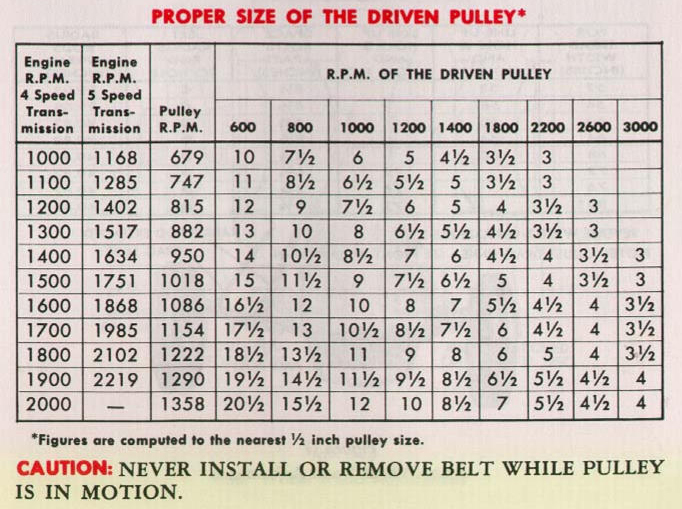
The A.S.A.E. standard belt speed for farm tractors is 3000 to 3200 feet per minute. With the standard nine-inch belt pulley on the Model 641 Ford Tractor, the belt speed is 3199 feet per minute at 2000 engine R.P.M. as shown on the four speed Proof-Meter. On models equipped with the five speed transmission, the belt speed is 3013 feet per minute at 2200 engine R.P.M.
Belt driven implements which do not meet A.S.A.E. standards should be operated at the speed recommended by the manufacturer. To obtain this speed, select a driven pulley of the proper size from the table below.
WHEEL TREAD ADJUSTMENTS
The unique design of the Ford Tractor permits a wide range of front and rear wheel adjustments which can be made quickly and easily.
Front Wheel Tread Adjustment: The front wheels are adjustable from 52 to 76 inches in 4 inch spacings. To change the tread width, raise the front end of the tractor with a jack and remove the bolts which hold the outer axle sections to the center section. Move the front wheels apart until the desired tread width is obtained (see Figure 17), then replace the bolts and tighten securely. Always leave one or more open holes between the bolts.
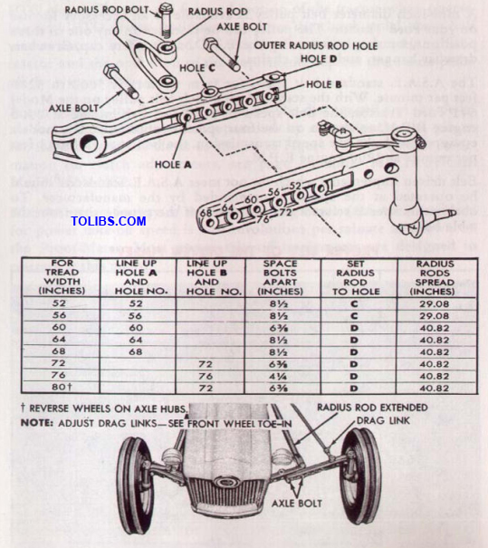
When absolutely necessary, an 80 inch tread width can be obtained by setting the axle for the 72 inch tread width and then reversing the wheels.
NOTE: When front wheel adjustments are made, the drag links must be adjusted to obtain proper front wheel toe-in. See page 49, under MAINTENANCE.
Rear Wheel Tread Adjustments: The tractor rear wheels are adjustable to the same tread widths as the front wheels. Tread width settings are made by changing the position of the steel discs and the rims to any of the positions from 52 inches to 76 inches shown in Figure 18. To change from the 52 inch tread width to the 72 inch width, it is only necessary to change the wheels from one side of the tractor to the other. Two other wheel changes are similar as shown at the top of Figure 18.
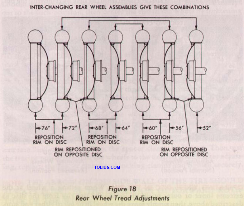
NOTE: THE ARROW ON THE SIDE WALL OF THE TIRE SHOULD ALWAYS POINT IN THE DIRECTION OF FORWARD ROTATION OF THE WHEEL.
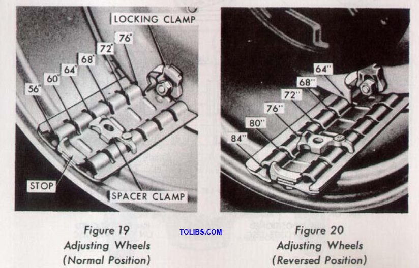
POWER ADJUSTED REAR WHEELS: If your Ford Tractor is equipped with Power Adjusted Rear Wheels, you will be able to change the rear wheel tread width quickly and easily by means of tractor power. The wheels may be spaced from 56 to 84 inches in 2 inch intervals. For tread widths of 56 to 76 inches, adjust the wheels, one at a time, as follows.
LOOSENING TIRE RIM FROM DISC: Loosen the nuts on the three locking clamps (see Figure 19), slide the clamps toward the center or retracted position, then retighten the nuts securely. Move the tractor until the wheel tread spacer clamp (Figure 19) is at the top of the wheel, then remove the spacer clamp from the disc by removing the nut.
OPERATING WHEEL DISC IN THE RIM: When setting a wheel at the extreme inner or outer position, loosen the tire rim from the disc as described above, then simply move the wheel in or out to either end stop.
For settings between 56 and 76 inches, first move the wheel to the extreme outer position by engaging the clutch, with the tractor engine at idle speed. Use reverse gear for the left wheel and forward gear for the right wheel.
NOTE: Brake the opposite wheel slightly and allow the tractor to creep forward or rearward while the wheel is being adjusted.
Next, place the spacer clamp in the channel thread bar which has stops at each end. Position the clamp for desired tread width and secure as shown in Figure 19. These settings will permit a full revolution, or adjustment of 2 inches for the wheel.
Rotate the disc back into the rim by engaging the clutch with the engine at idling speed. Use reverse gear for the right wheel and forward gear for the left wheel. Disengage the clutch as soon as the disc strikes the spacer clamp.
SECURING RIM IN POSITION: Move the tractor so that the spacer clamp can be replaced at the top of the wheel, then remove the clamp from the rim and reinstall it in the wheel. Tighten the nut securely. Loosen the nuts which hold the three locking clamps. Move the clamps out to the lock position, then center the rim in the wheel by tightening the bottom locking clamp. Secure the remaining two clamps. Tighten the nuts in sequence, and make sure the clamps are positioned at approximately the same angle.
NOTE: Check the nuts for tightness after the tractor has been operated for a short time.
CHANGING WHEEL DISCS: To obtain a tread width setting of 80 inches, it is only necessary to power-adjust the wheels to a normal 60” setting (see Figure 19), then reverse the wheels on the tractor. The 84* setting is obtained in the same manner by setting the wheels at 56' and reversing them on the tractor. With the wheels in the reversed (dish in) position, it will be necessary to set the spacer clamp and locking clamps from the inside of each wheel when making adjustments. See Figure 20. Disengage the spacer and the locking clamps, move the wheel to its extreme "in" position and set the spacer clamp as desired. Then, use the tractor power to adjust the wheels to the desired width. After adjusting, replace the spacer clamp and locking clamps and tighten securely.
NOTE: THE ARROW ON THE SIDE WALL OF THE TIRE SHOULD ALWAYS POINT IN THE DIRECTION OF FORWARD ROTATION OF THE WHEEL.
WHEEL WEIGHT
To assure sufficient traction for maximum performance in heavy draft operations, weight should be added to the Ford Tractor.
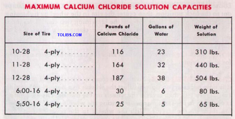
Liquid Ballast: It is a common practice to add weight by filling the rear tractor tires with liquid. A solution of calcium chloride is recommended because of its lower freezing point, and greater weight per gallon than water.
The use of liquid ballast in the front tires will help counter-balance heavy rear mounted implements, and will further increase the traction and "pull-power” of your Ford Tractor in heavy draft operations.
The recommended liquid capacities for tires are shown in the table below. This table is based on a 90% fill of the tires with 5 pounds of calcium chloride per gallon of water. The addition of this amount of calcium chloride will prevent freezing in most locations. A 90% fill of tires requires special equipment. See your Ford Tractor and Implement Dealer. For valve level filling of the tires listed, multiply the respective figures in the table by .8 to obtain the necessary information.
Cait Iron: In heavy work such as plowing and discing, added weight is necessary in most cases to provide sufficient traction to utilize the maximum power of the engine. Special cast iron weights are available, at extra cost, in different sizes for use on the Ford Tractor. These individual weight sections can be easily attached to or detached from the wheels as the job requires. On lighter jobs, removal of the weights will increase the operating economy of your tractor. The following chart describes the different types of weights and their recommended usage.
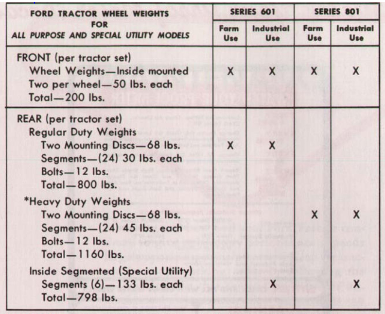
CAUTION: Under no circumstances should Heavy Duty Weights be used on Series 601 Tractors.
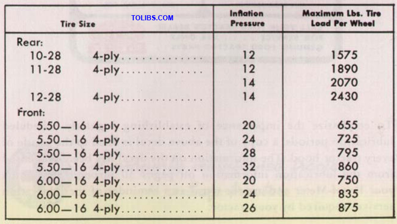
Weight added to the tires, together with the weight of the mounted implement and tractor, should not exceed the recommended weight to be carried by the tires. The following table lists the maximum recommended weight that can be carried without overloading the tires.
To emphasize the importance of establishing regularly scheduled lubrication periods, a copy of the above decal is fixed to the inside of every tractor hood. The information on the decal has been condensed from the lubrication information on pages 30 through 35. Watch your Proof-Meter and use the decal as a reminder of the lubrication services required by your tractor.
MAINTENANCE
How long and how well your Ford Tractor continues to give satisfactory performance depends largely upon proper maintenance. Keep the tractor in good working order by following the instructions in this section on lubrication, mechanical maintenance, minor adjustments and storage.
When major overhauls become necessary, see your Ford Tractor and Implement Dealer. He is interested in you and your tractor, and is properly equipped to meet your service needs.
PRE-DELIVERY INSPECTION
Before your tractor was delivered to you, the dealer performed a predelivery inspection which is the first step in the maintenance schedule of your tractor. Some of the more important items checked by your dealer are the cooling system, front end, engine, transmission, hydraulic system, rear end, and the general physical condition of your new tractor. A detailed listing of the inspections performed is shown on your Service Policy under the Pre-Delivery and 50-Hour Inspection Reports.
50 HOUR INSPECTION
After you have operated your tractor for a period of fifty hours, see your Ford Tractor and Implement Dealer. At this time, he will perform the factory recommended 50-Hour Inspection, without charge, except for lubricants. Remember that the dealer is interested in your tractor’s performance. See him periodically for continued good service.
LUBRICATION
Since your tractor will be subjected to a variety of operating conditions, it is extremely important that all moving parts be lubricated at the proper time. Avoid causing serious damage to your tractor by using clean containers and recommended grades of lubricant. The following guide describes, in hourly intervals, all of the lubrication services required by your tractor. These time intervals are based on average working conditions. When operating under extremely hot or dusty conditions, lubricate the tractor more frequently. The location of the lubrication points described in the lubrication guide are shown in Figures 25 and 26 on pages 34 and 35.
SERVICE DAILY OR EVERY TEN HOURS
Crankcase Ventilating System: Remove the element in the Rocker Arm Cover Breather and clean with a suitable solvent. Coat the element with light engine oil before replacing. Oil Filler Breather Cap: Remove the element, clean the entire assembly with solvent and coat the element with light engine oil.
Air Cleaner: Remove the oil cup and clean with a suitable solvent. Refill the cup with 1.3 pints of engine oil for Series 801 tractors, 0.8 pints for Series 601 tractors. (Under extremely dusty conditions, service more often.)
Pressure Type Fittings: Clean the fittings on the Lift Rod Leveling Box and Fork, Front Axle Spindles, Clutch Pedal and Steering Drag Links. Apply pressure gun grease and wipe the fittings clean. See Figure 25.
Distributor: Place a few drops of seasonal engine oil in the oil cup. Do not over lubricate. (See Figure 22.)
Crankcase Dip Stick: Remove the dip stick from the right side of the engine crankcase. Always wipe the dip stick with a clean cloth, replace it and then remove it again to determine the oil level. Maintain the level at the full mark with a good grade of heavy duty or premium engine oil. (See SERVICE EVERY 100 HOURS.)
Hydraulic System Dip Stick: Check the level of the hydraulic oil on the dip stick and maintain at the full mark with the proper lubricant as recommended under SERVICE EVERY 600 HOURS. When checking the hydraulic oil level, always be sure all hydraulic cylinders are fully extended.
SERVICE EVERY 100 HOURS
Engine Crankcase: Change the engine oil in your new tractor at the 50 Hour inspection and every 100 hours of operation thereafter. Drain the oil after the engine has reached normal operating temperature. Refill the crankcase with four quarts of good heavy duty or premium engine oil and add one extra quart of oil if the filter cartridge is replaced.
- SAE 30 - Temperatures consistently above 90° F.
- SAE 20 - Temperatures between 90° F. and 32° F.
- SAE 20W - Temperatures between + 32° and -f- 10° F.
- SAE 10W - Temperatures between + 10° F. and - 10° F.
- SAE 5W - Temperatures below - 10° F.
Rear Axle: Remove the rear axle inspection plug (11), Figure 25, and check the level of the oil. If necessary, add oil. (See SERVICE EVERY 600 HOURS.)
Transmission:Remove the transmission oil level inspection plug (19), Figure 2 5, and add oil, if required. (See SERVICE EVERY 600 HOURS.)
Steering Housing: Check the oil level at the steering gear case plug (17), Figure 25, and add lubricant as required. Use extreme pressure gear lubricant SAE 90 in the summer and SAE 80 in the winter.
Power Steering Pump Reservoir:Check the oil level every 100 HOURS OF OPERATION. Maintain the oil level as indicated on the dipstick attached to the filler cap. Refer to the decal on the reservoir.
CAUTION: Use only AUTOMATIC TRANSMISSION FLUID-TYPE "A” in the Power Steering System. Always use clean fluid. Dirty fluid may cause extensive damage to the system.