1960 Ford Tractor 501 Offset Owner’s Manual
FOREWARD
Your new Series 501 Ford Offset Tractor is basi cally the same as the Model 741 tractor with the required modifications to obtain the offset feature. Model 541 is the standard off set tractor, Model 541-4 is the high clearance off set. Information given in this manual covers only the portions of your tractor that are different from the Model 741 and should be used as a supplement to the regular owner's manual included in your owner's envelope.
TRACTOR AND IMPLEMENT DIVISION FORD MOTOR COMPANY SERVICE DEPARTMENT
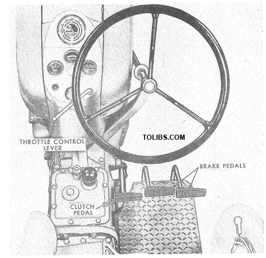
Figure 1 Controls and Instruments CONTROLS
The design of the offset tractor necessitated the relocation of some of the controls as shown in Figures 1 and 2. The throttle control lever is located on the right side of the instrument panel. Push the lever up to increase the engine speed. On diesel engine equipped tractors, the throttle lever must be pulled all the way down to shut the engine off. The clutch pedal, brake pedals, brake pedal locks and power take-off lever are located as shown. The operation of these controls remain the same as described in the Model 741 owner's manual supplied with your tractor.
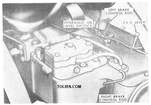
Figure 2 Brake Pedal Locks and P.T .O. Lever
OPERATION
Attaching Implements: Most implements can be easily and quickly attached to the tractor three point linkage. Operation of the lift links, leveling crank 'and three hole rocker shown in Figure 3 are the same as described in the Model 741 owner's manual.
The adjustable top link may be adjusted to suit implement operation requirements by releasing the lock and rotating the sleeve until the desired length is obtained. The standard length of 25 inches (as opposed to 23 on the Model 741) is obtained by adjusting the link as shown on a decal located on the sleeve (see Figure 3). Drawbar: The linkage drawbar, Figure 4, which fits between the lower links is standard equipment on the offset tractor. The drawbar stays, Figure 4, should always be used with the linkage drawbar. Lock the lift control lever in the down position, see insert, Figure 4, to prevent the operator from using tne nyoraunc system. the swinging drawbar, sold as an accessory, can be used by removing the left link as shown in Figure 5.
WHEEL TREAD ADJUSTMENT
Front Wheel: The front wheel tread adjustment for the offset tractor can be varied from 40" to 78" in approximately 4" spacings. To change the tread width, place a jack under the forward end of the transmission housing and lift the front wheels off the ground. Adjust one axle section at a time by first removing the two hex head bolts (1), Figure 6, that secure the axle half to the center axle. Then, remove the connecting rod square head set screw (2). Position the axle half in or out to obtain the desired wheel spacing. Replace the hex head axle bolts (1), making sure there are at least two holes between each bolt. Install the flat washers and nuts and tighten the nuts evenly.
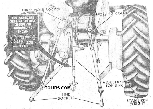
Figure 3 Leveling Cronk and Adfustable Top Link
With the front wheels in the straight ahead position, align the hole in each spindle arm sleeve with the proper dimple in the connecting rod. This is best accomplished by looking through the hole in the sleeve to locate the dimple in the rod. Install the set screw (2), and securely tighten the lock nut.
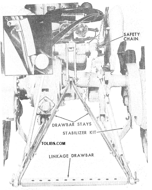
Figure 4 Drawbar Stays and Safety Chain
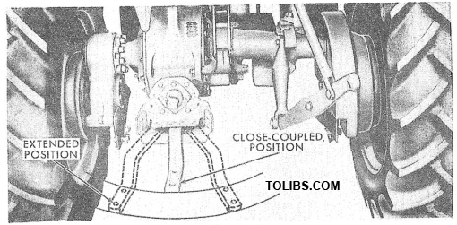
Figure 5 Swinging Drawbar
An additional wheel spacing of 86" can be obtained by reversing the front wheels at the 78" spacing. Normally, it will not be necessary to make a toe-in adjustment after changing tread width, but it should be checked after changing tread width.
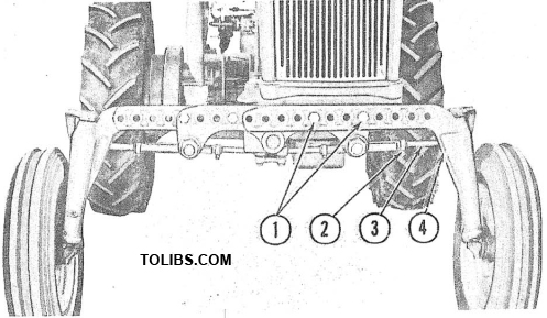
Figure 6 Front Axle Adjustment
Rear wheels: The rear wheel adjustable from 40 to 68 inches. The 40" tread width can be obtained only when standard 10" tires are used. Tread width settings are made by changing the position of the wheel discs and the rims to any of the positions shown in Figure 7. To change from the 40 inch tread width to the 68 inch width, it is only necessary to change the wheels from one side of the tractor to the other. Three other wheel changes are similar as shown at the top of Figure 7.
NOTE: Figure 7 shows only one tractor wheel. Additional spacings of 72 and 76 inches can be obtained with the use of 2 inch or 4 inch spacers available from your Ford Tractor and Implement Dealer.
INTER-CHANGING REAR WHEEL ASSEMBLIES GIVE THESE COMBINATIONS RIM REPOSITIONED ON OPPOSITE DISC RIM REPOSITIONED ON OPPOSITE DISC
Toe-in adjustment is accomplished by loosening the spindle connecting rod clamp bolts (4), Figure 6, and the set screw (2). Lengthen or shorten the connecting rods (3), by turning them. Correct toe-in is obtained when a difference of 1/4 exists between the tread widths measured at hub height at front end of the front tires. When adjusting toe-in, always make certain both rods are the same length by measuring and comparing the rod lengths. Tighten the clamp bolts (4), and set screws (2), securely.
To provide greater stability of the offset tractor, a 300 lb. stabilizer weight, shown in Figure 3, has been added to the right-hand final drive housing. This weight remains on the tractor at all times and need not be removed for making wheel tread adjustments.
Wheel Weight: Liquid ballast or cast iron weights can be used on the offset tractor. The following information should be used in conjunction with the information in the Model 741 owner's manual:
MAXIMUM CALCIUM CHLORIDE SOLUTION CAPACITIES (90% Fill)
- Size of Tire 10 x 28 10 X 38
- Pounds of Calcium Chloride 116 157
- Gallons of Water 23 3
- Weight of Solution 310 Lbs. 416 Lbs.
- Inflation Pressure 12 12
- Maximum Lbs. Tire Load Per Wheel 1575 1820
MAINTENANCE
Clutch Adjustment: To obtain proper operation and to insure the longest possible clutch life, it is necessary to maintain the recommended clutch pedal height and pedal free travel adjustments. For proper height the clutch pedal should be in line with the brake pedal. To adjust the pedal height, turn the adjusting screw, shown in Figure 8, out to decrease height or in to increase height. Pedal free travel is the distance the clutch pedal can be pushed down before resistance is met.
To adjust pedal free travel, loosen the clevis lock nut and turn the clevis in to decrease free travel, or out to increase free travel. Set the pedal free travel at 1-1/2 inches, see Figure 8. Make sure the lock nut is securely tightened after adjusting. The brake and clutch pedals have pressure type grease fittings, see Figure 8, which are to be serviced every 100 hours of operation.
BRAKE ADJUSTMENT
Brake adjustment is accomplishcd in the same manner as covered in the Series 701 Ford Tractor Owner's Manual. However, in the case of the right rear wheel, it will be necessary to adjust the brake from directly under the stabilizer weight. Due to the space limitation, a short screwdriver will be required. When correctly adjusted, the brake pedal arms should contact the step plate, see Figure 8.