Ford Truck WorkShop Manual
Ford Truck WorkShop Service Repair Manual
This manual is divided into five volumes: 1 - Chassis, 2 - Engine, 3 and 4 - Electrical and Body, 5 - Maintenance and Lubrication. These volumes should provide Service Technicians with complete information covering normal service repairs on all 1971 model trucks built by the Ford Companies in the U. S. and Canada. As changes in the product occur, this information will be updated by Technical Service Bulletins. When issued, TSB information always supersedes that published herein.
Within each volume, information is grouped by system or component plus "General Service" parts which contain information which is common to several similar components.
The table of contents on the first page of each volume indicates the general content of the book and provides a handy tab heater to make it easy to find the first page of each "Group". That page will contain an index to "Parts" and the first page of each "Part" contains a detailed index which gives page location for each service operation covered. Page numbers are consecutive in each "Part"
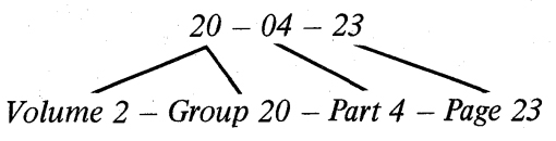
To make reference easier, information has been broken down into smaller units so that essentially there is now one "Part" for each component or system. Group numbers indicate the volume in which the group may be found.
Indicates:
The descriptions and specifications in this manual were in effect at the time this manual was approved for printing. Ford Marketing Corporation reserves the right to discontinue models at any time, or change specifications or design, without notice and without incurring oblication.
Identification Codes
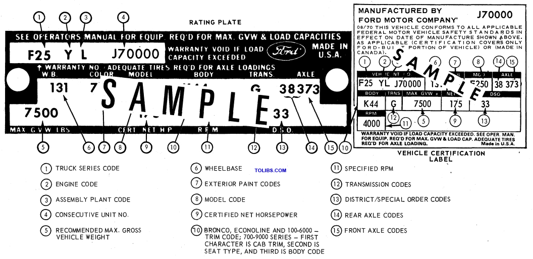
Typical Truck Rating Plate and Vehicle Certification Label
The Vehicle Certification Label (V.C. Label) is attached to the rear face of the driver's door. The upper half of the label contains the name of the manufacturer, the month and year of manufacture and the certification statement. The V.C. Label also contains the Vehicle Identification Number.
The remaining information codes on the V.C. Label are the same as the Truck Rating Plate Codes (Fig. 1). Vehicle codes shown on the Truck Rating Plate are explained in the following paragraphs.
RATING PLATE
Figure 1 illustrates a typical Truck Rating Plate. On light and medium cowl and windshield vehicles, the Rating Plate is mounted on the right side of the cowl top panel under the hood. On stripped Parcel Delivery vehicles, the rating plate is placed in an envelope and included in the Boxed Items parts. On Bronco models, the plate is mounted on the inside panel of the glove compartment door. On all other vehicles, the Rating Plate is mounted on the rear face of the left front door.
VEHICLE WARRANTY NUMBER
The Warranty Number is the first line of numbers and letters appearing on the Rating Plate (Fig. 1). The first letter and two numbers indicate the truck model and series (the letter prefix identifies the type of body or cab and the numbers are the first two numbers of a truck series). The letter following the truck series code designates the engine identification code. The letter following the engine identification code indicates the assembly plant at which the vehicle was built. The remaining numbers indicate the consecutive unit number. The charts that follow list the various vehicle warranty number codes.
VEHICLE DATA
the Vehicle Data appears on the Rating Plate on the two lines following the Warranty Number. The first three digits under W.B. designate the wheelbase in inches. The one or two letters under COLOR identify the exterior paint color (two letters designate a two-tone). The letter and three digits under MODEL designate the truck model within a series. The letter and numerals under BODY designate the interior trim and body type (the letter identifies the interior trim scheme and the numberals identify the body or cab type). The transmission installed in the vehicle is identified under TRANS by either a numeric or alphabetical code (if two symbols appear, the first identifies the auxiliary transmission, if so equipped, and the second symbol identifies the main transmission). A letter and a number or two numbers under AXLE identify the rear axle ratio (when required, a letter is also stamped behind the rear axle code to identify the front axle capacity). The maximum gross vehicle weight in pounds is stamped under MAX. G.V.W. Following MAX. G.V.W., the horsepower rating of the engine with which the vehicle is equipped is stamped under CERT. NET H.P. and the rpm required to develop the given horsepower is stamped under R.P.M. Two-digit number is ' stamped under D.S.O. to identify the district which ordered the vehicle. If the vehicle is built to special order (Domestic Special Order, Foreign Special Order, Limited Production Option, or other special order), the complete order number will also appear under D.S.O. The charts that follow list the various vehicle data codes.
General Wheel and Tire Service
DESCRIPTION
STEMCO SEALS
When servicing wheel assemblies equipped with Stemco seals any special tools refered to can be obtained only through a Stemco Warehouse Distributor. Refer to Specifications at the end of this Part to determine tool requirements.
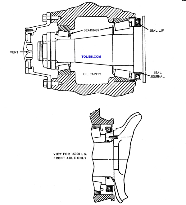
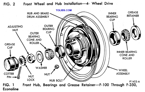
Stemco wheel seals are a Regular Production Option for 1971. They will be available for both front and rear wheel application on medium and heavy duty trucks, except on medium trucks equipped with 5000 or 5500 pound capacity axles. When used on the front wheels oil is used for lubrication, and just a coating of long life lubricant is required. Rear wheel bearings also use oil but must be packed with long life lubricant (ESA-M1C75-B) before installation. Wheel bearing adjustment procedures are not changed. Sectional views of both front and rear seal installations are shown in Figs. 1, and 2. An exploded view of the Stemco front wheel hub and components is shown in Fig. 3. Reference to these illustrations should assure a satisfactory installation.
Front Hub Seal Installation
Clean all parts before starting the installation.
- Oil the spindle and push the axle ring flush against the axle face where applicable.
- Remove all burrs from the wheel hub bore seal area and clean thoroughly.
- Position the seal in the hub bore (Part Number Up).
Drive the seal into position using the correct tool. It must be perfectly square with the bore, and bottom evenly. Install the wheel and adjust the bearings as outlined in Part 11-10, Section 3. Install the Stemco hub cap. Remove the filler plug and add oil (ESW-M2C105-A SAE 90). Double check the oil level before releasing the vehicle for service. Oil level must be between the oil level line on the hub cap and 1/4-inch above the line.
Rear Hub Seal Installation
- Thoroughly clean the axle spindle.
- If the spindle shoulder is scored or pitted apply a thin coat of Permatex No. 2.
- Position the axle ring and drive it into position flush with the inner bearing shoulder using the correct tool. Procedures vary with different applications. Refer to the instructions packed with each seal set.
- Remove all burrs and protrusions from the oil seal area of the wheel hub.
- Pack the inner bearing cone with M1C75-B and position it in the bearing cup.
- Position the oil seal at the mouth of the bore and drive it squarely into position using the correct tool. The seal must be evenly bottomed.
- Take special care not to damage the oil seal while installing the wheel.
- Fill the wheel cavity with oil before installing the outer bearing. 9. Pack the outer bearing with M1C75-B and install it and then adjust the bearings as outlined in Part 11-11, Section 3.
- Inspect axle shaft gasket mating surfaces for nicks, burrs, and dirt; then install the axle shaft.
- Check the rear axle lube level and add oil if required.
CLEANING AND INSPECTION
WHEELS
Wheel stud nuts should be inspected and tightened in the first 500 miles, to avoid accidental loosening of the wheels. Loose wheel stud nuts may cause shimmy and vibration. Elongated stud holes in the wheels may also result from loose stud nuts. Keep the wheels and hubs clean. Stones or lumps of mud wedged between the wheel and drum will unbalance a wheel and tire. Check for damage that would affect the runout of the wheels. Wobble or shimmy caused by a damaged wheel will eventually damage the wheel bearings. Inspect the wheel rims for dents that could permit air to leak from the tires.
TIRES
The tires should be checked frequently to be sure that the air pressures agree with those specified for the tires and vehicle model. Inspect the tire treads, and remove all stones, nails, glass, or other objects that may be wedged in the tread. Check for holes or cuts that may permit air leakage from the tire, and make the necessary repairs.
Inspect the tire side walls for cuts, bruises, and other damage. If internal damage is suspected, demount the tire from the wheel for further inspection and repair or replacement. Check the tire valve for air leaks, and replace the valve if necessary. Replace any missing valve caps. On F-100, 250, 350 and Econoline models, it is important that the front tires and wheels be balanced. Fig. 4 describes common tire wear conditions.
FRONT WHEEL BEARINGS
Wheel bearings are adjustable to correct for bearing and spindle shoulder wear. Satisfactory operation and long life of bearings depend on proper adjustment and correct lubrication. If bearings are adjusted too tightly, they will overheat and wear rapidly. An adjustment that is excessively loose will cause pounding aiH contribute to uneven tire wear, steering difficulties and inefficient brakes. The bearing adjustment should be checked at regular inspection intervals.
Front hubs and bearings should be cleaned, inspected and lubricated whenever the hubs are removed or at the mileage/time periods indicated in the maintenance schedule. New hub grease seals should be installed when the hub is removed. An imperfect seal may permit bearing lubricant to reach the brake linings resulting in faulty brake operation and necessitating premature cleaning or replacement of linings.
Wheels and Tires Drop Center Rim
FRONT WHEEL ASSEMBLY
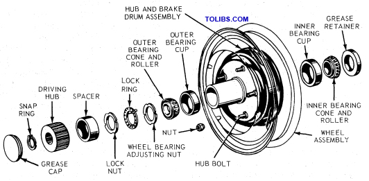
Each front wheel and tire assembly is bolted to its respective front hub and brake drum or rotor assembly. Two opposed tapered roller bearings are installed in each hub (Figs. 1 and 2). A grease retainer is installed at the inner end of the hub to prevent lubricant from leaking into the drum. The entire assembly is retained to its spindle by the lock nut and/or adjusting nut and cotter pin.
FRONT WHEEL ASSEMBLY - 4-WHEEL DRIVE
The front axles used on 4-wheel drive models are covered in Group 15, Parts 15-30, 15-31, 15-32 and 15-33 of this manual.
REAR WHEEL ASSEMBLY
The rear wheel, hub, and drum assemblies are connected to the rear axle shaft flanges and ride on two opposed tapered roller bearings. The inner end of each axle shaft is splined to the engine powered differential.
REMOVAL AND INSTALLATION
WHEEL REPLACEMENT
Light Vehicles
Removal:
- Pry off the hub cap (if the vehicle is so equipped), and loosen but do not remove the wheel stud nuts.
- Raise the truck until the wheel and tire clear the floor.
- Remove the wheel stud nuts and the wheel and tire from the hub and drum.
Installation:
- Clean all dirt from the hub and drum. The replacement wheel and tire must be clean.
- Position the wheel and tire on the hub and drum, and install the wheel stud nuts. For proper balance, line up the notch on the drum with the valve stem on the wheel. Tighten the stud nuts enough to hold the wheel firmly in place. Always tighten alternate nuts to draw the wheel evenly against the hub and drum. On dual wheels, be sure to back off the outer nut before tightening the inner nut. Then tighten the outer nut. Some dual wheels have mounting bolt holes which are alternately flared inward and outward. These surfaces must be mated when the wheels are mounted.
- Lower the vehicle to the floor, and tighten the wheel stud nuts to the specified torque. On a new vehicle, and each time a wheel and tire is installed, the wheel nuts should be checked for tightness. When installing the hub cap, notice the wheel nubs. The hub cap should be positioned on the wheel over one of the retaining nubs and the two locating nubs. Be sure that the lip of the hub cap is firmly seated in the groove of the retaining nub, and then force the cap over the second retaining nub. Any other procedure necessitates heavy pounding with possible damage to the hub cap.
Medium Vehicles
Removal:
- Loosen but do not remove the wheel stud nuts.
- Raise the vehicle until the wheel and tire clear the floor.
- Remove the wheel stud nuts and the wheel and tire from the hub and drum.
Installation:
- Clean all dirt from the hub and drum. The replacement wheel and tire must be clean.
- Position the wheel and tire on the hub and drum, and install the wheel stud nuts. For proper balance, line up the notch on the drum with the valve stem on the wheel. Tighten the stud nuts enough to hold the wheel firmly in place. Always tighten alternate nuts to draw the wheel evenly against the hub and drum. On dual wheels, be sure to back off the outer nut before tightening the inner nut. Then tighten the outer nut.
- Lower the truck to the floor, and tighten the wheel stud nuts to the specified torque. On new vehicles, and each time a wheel and tire is installed, the wheel nuts should be checked for tightness.
TIRE REPLACEMENT PRECAUTIONS
The tire must be completely deflated before removal, and the bead must not be damaged by a tire iron. After installation, a tube tire should be inflated to recommended pressure, deflated, and then inflated again to insure that the tube is not folded inside the tire. Be sure the tube flap is properly positioned before inflating the tire. On F-100 and 250 series, it is important that each front tire and wheel be balanced. When installing tires on vehicles equipped with Safety Ledge rims, thoroughly lubricate the tire beads. Inflate the tire until the bead seats against the rim of the wheel, then deflate to the specified pressure.
TIRE REMOVAL AND MOUNTING-DROP CENTER RIM
The drop center rim (Fig. 3) is used for either tube or tubeless tires.
- After completely deflating the tire by removing the valve core, loosen the beads, and force them into the drop center of the rim.
- Using a pair of tire irons, pry the wheel out of the tire.
Mounting Tire to Wheel
- After inspection and cleaning of the tire and wheel, install the valve core in the inner tube and inflate the tube until it is barely rounded out.
- Position the tube in the tire, soap the tire beads, and force the bottom bead into the drop center.
- At a point on the wheel opposite the valve, insert a tire iron between the top bead and the rim, prying the bead over the rim.
- Hold this iron in position, and with another iron, pry the bead into position all the way around the rim. Do not use a hammer or mallet to force the beads over the rim.