Ford Tractor 1100 2112 Workshop Manual

Ford 1100 2112 Tractor Workshop Service Repair Manual
DUAL DIMENSIONS
This service manuai provides specifications in both the Metric (SI) and U.S. Customary systems of measurement. The first specification is given in the measuring system used during manufacture, whiie the second specification (given in parenthesis) is the converted measurement. For instance, a specification of "0.28 mm (0.011 inch)" wouid indicate that the equipment was manufactured using the metric system of measurement and the U.S. equivaient of 0.28 mm is 0.011 inch.
FRONT AXLE AND STEERING SYSTEM
FRONT AXLE (TWO WHEEL DRIVE)
All Models So Equipped:
The front axle may be fixed tread width type or adjustable type for 1100, 1110, 1200, 1210, 1300, 1810, 1500 and 1510 models as shown in Figs. 1, 2 and 3. The adjustable axle used on 1700, 1710, 1900 and 1910 models is shown in Fig. 4. Adjustable axle used on 1710 Offset tractor is shown in Fig. 5, and adjustable axle used on 2110 tractor is shown in Fig. 6.
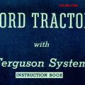
Fig. 1 exploded view of fixed tread front axle assembly used on two wheel drtve 1100, 1110, 1200 and 1210 models.
- Front wheel hub outer half
- Nut
- Outer bearinjj
- "0" ring
- Collar
- Inner bearing
- Seal
- Seal
- Wheel hub inner half
- Spacer
- Spindle
- Oil seal
- Bearing washers
- Needle thrust bearing
- Bushings
- Axle
- "0" ring
- Washer
- Steering arm
- Cotter pin
- Castelated nut
- Washer
- Washer
- Shim
- Shim
- Bushing
- Pivot shaft
Front wheel toe-in is set by adjusting the length of the tie rod. Toe-in should be 0-5 mm (0-3/16 inch) on all models. Clearance between axle pivot shaft and bushings (26-Figs. 1, 2, 8, 4, 5 and 6) should be 0.02-0.15 mm (0.001-0.006 inch). Bushings should be renewed if clearance exceeds 0.30 mm (0.012 inch).
Axle end play should not exceed 0.20 mm (0.008 inch). If end play is excessive, renew thrust washers (23) and/or add shims (24) as required.
When renewing spindle bushings (15), the top bushing should be pressed into bore until bushing is 4.7 mm (3/16 inch) below top surface of axle on models equipped with an "0" ring (17-Figs, 1 and 2) at top of spindle (11). On models equipped with a lip type seal (12-Figs. 3, 4, 5 and 6) at top of spindle, top bushing should be pressed into bore until top of bushing is 7 mm (9/32 inch) below top surface of axle. Install seal with lip facing upward.
Front wheel bearings should be removed, cleaned, inspected, renewed if damaged and packed with a good quality No. 2 EP lithium base grease after each 600 hours of operation. Tighten wheel bearing retaining nut (2) until slight drag is noticed while rotating wheel hub, then loosen nut to first castellation and install cotter pin.
FRONT AXLE (FOUR WHEEL DRIVE)
The front axle of four wheel drive models includes the differential assembly, axle housings, drive shafts, universal joints and final drives. Refer to appropriate paragraphs 3 through 12 for service to components. Tie rod length should be adjusted to provide front wheel toe-in of 0-5 mm (0-3/16 inch) on all models.
Models 1100-1200-1300-1500-1700-1900 So Equipped
REMOVE AND REINSTALL
To remove the complete front drive axle assembly, first raise front of tractor and place a support behind the axle. Detach drag link from steering arm. Place front wheel drive control lever in "disengaged" position. Loosen clamps that attach drive shaft cover at the rear. Support axle to prevent tipping, then remove cap screws attaching axle pivot brackets to front support. Carefully lower axle until it can be moved forward out of drive shaft splines.
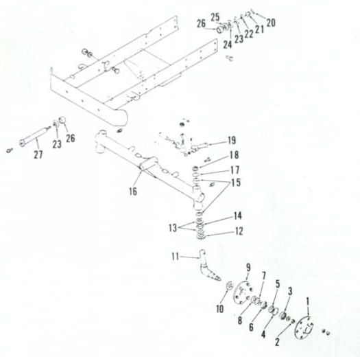
Ftg. 4 - Expioded view of adiustabie front axle used on 1700, 1710, 1900 and 1910 models with two wheei drive. Refer to Fig. 3 for iegend except for the foiiowing:
- 35. Spacer
- 36. Spacer
- 37. Retainer
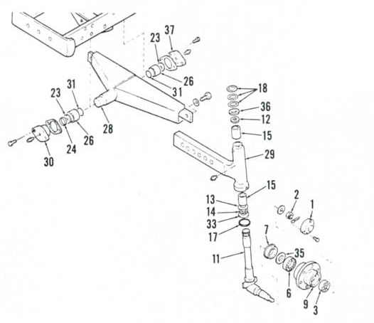
Fig. 2-Exploded view of adiustabie tread width front axle avaliabie on 1100, 1110, 1200 and 1210 models. Refer to Fig. 1 for legend except for the following:
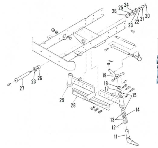
- 28. Axle center member
- 29. Axle extensions
Inspect axle pivot bushings (13 and 36-Figs. 7, 8 and 9) for wear or damage. Renew bushings if clearance between differential case trunnions and bushings exceeds 0.35 mm (0.014 inch). Use a suitable driver to install bushings and make certain bushings are recessed 4 mm (5/32 inch) in pivot carriers to allow for installation of "0" rings (14 and 35).
When reinstalling axle, observe the following: Move axle assembly carefully into position while sliding drive shaft splines and pinion shaft splines into coupling. Tighten screws attaching pivot brackets to front support, then check axle housing fore and aft end play. Desired end play is 0.30 mm (0.012 inch) or less. If end play exceeds 0.50 mm (0.020 inch), shims should be installed in front pivot bracket as required to obtain desired end play.
Stop bolts (49 - Figs. 7, 8 and 9) should be adjusted to provide correct turning radius and to prevent drag link interference. Stop bolt setting is measured from head of bolt to surface of mounting pad. Correct length is 24 mm (15/16 inch) for 1100 and 1200 models; 82 mm (I-V4 inches) for 1300 and 1500 models 40 mm (1-9/16 inches) for 1700 and 1900 models.
OUTER DRIVE ASSEMBLY
To remove the outer drive, first remove wheel and tire. Detach drag link and tie rod from axle steering arm. Remove plates and seal parts (65 through 68-Figs. 7, 8 and 9). Support the outer drive unit, then unbolt and remove king pins (47 and 50). Withdraw assembly from axle housing (43).
On early 1100 and 1200 models, universal joint (48-Fig. 7) is integral with shaft for outer pinion gear (53). To remove universal joint first separate outer cover (63) from housing (57) and remove snap ring (55) from end of shaft. Tap universal joint and shaft out of bearings (52 and 54) and pinion gear. Remove wheel axle (64), gear (59), bearings and seals from outer cover and housing.
On late 1100 and 1200 models and all 1300, 1500, 1700 and 1900 models, pinion shaft is integral with the pinion gear (53-Figs. 8 and 9) and universal joint (48) can be removed without disassembling outer drive unit. To disassemble outer drive, remove snap ring from inner end of pinion shaft (53). Unbolt and separate outer cover (63) from housing (57). Remove nut and washer (71), then tap wheel axle (64) out of bearings and gear. Remove pinion gear, bearings and seals from housing and cover.
On all models, backlash between pinion gear (53) and final drive gear (59) should be 0.20-0.40 mm (0.008-0.016 inch). If backlash exceeds 0.70 mm (0.028 inch), renew bearings or gears as required. Clearance between king pins (47 and 50) and bushings (45) should be 0,02-0.12 mm (0.001-0.005 inch). Maximum allowable clearance is 0.30 mm (0.012 inch).
To reassemble, reverse the disassembly procedure. Note that shims (70-Fig. 8 and 9) are used on all except 1100 and 1200 models to adjust bearings (58 and 61) to zero end play.
BEVEL DRIVE GEARS AND DIFFERENTIAL
To disassemble front axle center section, first remove both outer drive assemblies as outlined in paragraph 4. Remove front axle assembly as outlined in paragraph 3. Drain oil from axle center housing.
The differential and ring gear (22 through 30-Figs. 7, 8 and 9) can be removed after unbolting and separating axle shaft housings from center housing (34). Bevel pinion (21) can be removed after removing nuts (15) from shaft. Retain all shims for use in reassembly. Shims (19) are used to adjust mesh of bevel pinion and ring gear. Shims (32 and 33) are used to adjust differential carrier bearing preload and bevel gear backlash.
To disassemble differential unit, unbolt and remove cover (30) from carrier (23). Remove retaining pin (27), then slide pinion shaft (26) out of carrier. Remove pinion gears (25), side gears (28) and thrust washers (24 and 29), Backlash between differential pinion gears (25) and side gears (28) should be 0.10-0.15 mm (0.004-0.006 inch) with a wear limit of 0.50 mm (0.020 inch) for 1100, 1200, 1300 and 1500 models. Backlash between pinion gears and side gears for 1700 and 1900 models should be 0.05-0.10 mm (0.002-0.004 inch) with a wear limit of 0.45 mm (0.018 inch). 'Renew thrust washers (24 and 29) and/or gears if backlash is excessive. Diametral clearance between pinion gears (25) and shaft (26) should be 0.10-0.30 mm (0.004-0.012 inch).
Ring gear (22) and pinion (21) must be renewed as a matched set. Cap screws attaching ring gear to differential carrier (23) should be tightened to the following torque: 30-34 N-m (22-25 ft.-lbs.) on 1100 and 1200 models; 30-40 N-m (22-30 ft.-lbs.) on 1300 models 60-70 N-m (44-51 ft.-lbs.) on 1500 models; 47-55 N-m (35-40 ft.-lbs.) on 1700 and 1900 models.
Install drive pinion (21) in center housing using shims (19) that were originally installed for initial assembly. To adjust pinion bearing preload, wrap a cord around pinion shaft as shown in Fig. 10. Use a spring scale to measure pull required to rotate the shaft. Tighten inner nut (15-Fig. 7, 8 or 9) until spring scale reading is 5-6 kg (11-13 pounds) for 1100 and 1200 models; 5V2-7 kg (12-13 pounds) for 1300 and 1500 models; 11-15 kg (24V4-33 pounds) for 1700 and 1900 models. Install washer (16) and tighten outer nut (15), then recheck rolling torque.
If differential carrier (23), cover (30), carrier bearings (31), ring gear and drive pinion, center housing (34) or axle shaft housings (43) were renewed, differential carrier bearing preload, ring gear to pinion backlash and gear mesh must be checked and adjusted as outlined in paragraphs 6 and 7. If none of these components are being renewed, reassemble differential and front axle installing original shims in their original locations.
DIFFERENTAL CARRIER
BEARING PRELOAD. To adjust carrier bearings, first attach right axle housing to center housing (34-Fig. 7, 8 or 9). Place housing in vertical position with center housing up. Assemble sufficient thickness of shims (32) in housing bore to make sure that ring gear will not contact drive pinion, then install differential assembly in center housing. Be sure that carrier bearing is properly seated in axle housing bore.
Position left axle housing over differential assembly using more shims (33) than will be required to ensure that there is clearance between axle housing and center housing. Install four equally spaced bolts around axle housing and tighten finger tight. Use a feeler gage to measure gap between the two housings, then remove left axle housing and subtract shims from shim pack (33) equal to the measured gap.