Ford Tractor 125, 145, 165 Operator’s Manual

SET-UP INSTRUCTIONS
DEFINITION OF DIRECTIONS
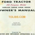
Reference to 'right" and "left" side of tractor is from operator's position when seated in normal operating position. Reference to "forward" and "rearward" is likewise from operator’s position. ut a light coating of oil on the steering wheel shaft before mounting the steering wheel.
- Straighten the front wheels.
- Remove the large plastic bushing, sponge washer and nut from the bag of parts.
- Place the plastic bushing on the steering column and then the sponge washer.
- Remove the steering wheel from the box of parts and position it on the steering column so that;
- The two spokes are horizontal.
- The notch is on the top half;
- The serrations in the wheel hub engage properly with those on the steering shaft.
- Thread the nut onto the steering shaft and tighten securely.
- Remove steering wheel cap from box of parts. Insert the tab of the cap into the notch inside the hub and push cap into the groove.
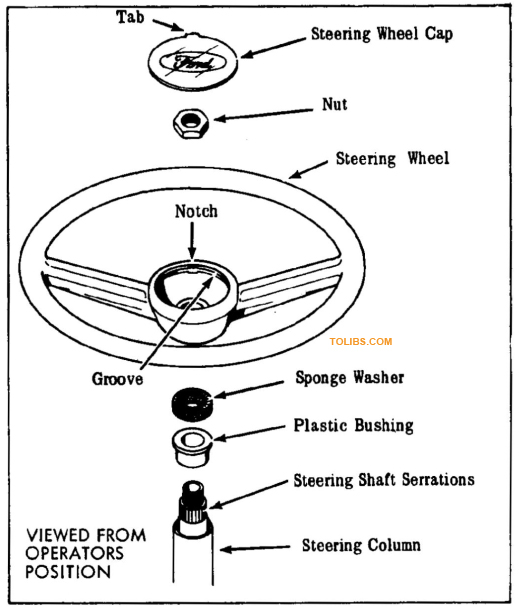
INSTALLING THE SEAT
- Remove the seat from box of parts and (4) 5/16-18 x 3/4 hex hd screws and lockwashers from bag of parts.
- Pull seat switch leads thru hole in seat mounting plate. Position seat over holes closest to seat pan hinge and secure in place with (4) screws and lockwashers.
- Assemble seat switch leads to connector in tool box.
PUTTING BATTERY IN SERVICE
With proper care the battery should give the long service life built into it. A battery which does not function properly is not necessarily worn out or defective.lt may only need a good recharge. If battery trouble occurs, a full recharge and test by a competent battery man is recommended.
IMPORTANT: Do not use the headlights more than one hour for every two hours of operation. For more frequent use, provide a supplementary charge to the battery.
The battery needs to be charged before it can be placed in service. You can do this yourself or have it done by your Authorized Dealer or an automotive service station. Two quarts (1.89 liters) of 1.265 specific gravity electrolyte are required to fill your battery and can be purchased from your dealer or local auto supply store. Proceed as follows:
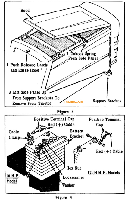
Note that the positive (+) terminal on the 16 H.P. battery is on the left hand side with the filler caps toward the front. The positive terminal on the 12-14 H.P. battery is on the right.
- Make sure all switches are in “off* position.
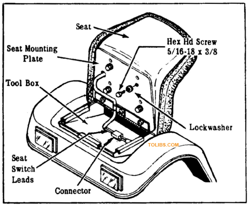
- Raise up the hood and remove the side panels (See Fig. 3).
- Disconnect the ground cable (black) from the negative (-) battery terminal. Then disconnect the positive cable (red) from the positive (+) terminal. Be sure to disconnect the negative cable first. Place both cables away from the battery.
- Remove the nut, lockwasher and washer from each battery mounting rod and remove the battery mounting bracket (See Fig. 4).
- Remove the battery from the tractor and place it on a wooden bench or a piece of wood or plastic. DO NOT SET THE BATTERY ON A CONCRETE FLOOR.
- Remove filler caps and fill battery with electrolyte to proper level (See Fig. 17). ALLOW BATTERY TO SIT FOR 20 MINUTES BEFORE PROCEEDING WITH STEP NO. 8.
- Before installing the electrolyte, study the instructions on the carton.
- With the filler caps still removed, place battery on charge at 3 amperes until gravity reading is 1.265-1.275. This should take approximately four hours. If room, battery and electrolyte temperatures are below normal, a longer charging period may be necessary to bring the specific gravity up to 1.265-1.275.
- Insert filler caps into filler holes and place battery on shelf in front of the instrument panel. BATTERY TERMINALS MUST BE TOWARD THE GAS TANK. (See Fig. 4).
- Remount the battery to the tractor as shown in Figure 4. Place the battery bracket against the battery. Install the J-shaped battery rods, washers, lockwashers and nuts and tighten snugly. Do not overtighten.
- Next, connect the two battery cables to the battery terminals (See Fig. 4). Note that the battery on the 16 H.P. model uses terminal clamps with hex nuts to secure the cables. The batteries on the 12 and 14 H.P. models use carriage bolts and nuts without the terminal clamps.
- The cable leading to the ignition components of the engine is the “hot” cable (red in color) and should be attached to the positive (4-) battery terminal in the following manner Insert the cable end through the positive terminal cap as shown in Fig. 4. Remove the nut from the carriage bolt or clamp provided and place cable eye onto threads. Secure cable eye in place with the nut.
- The cable attached to the tractor chassis is the ground cable (black in color) and is connected to the negative ( - ) battery terminal in the following manner: Remove the nut from the carriage bolt or clamp and place cable eye onto threads. Secure cable eye in place with nut just removed.
- Now apply a light coat of petroleum jelly or chassis lubricant to both terminals and cable ends to prevent corrosion.
- Slide the terminal cap over the positive battery terminal
SAFETY GUIDELINES FOR BATTERIES
- Use extra caution with an external battery chargei. If overcharging occurs the battery will release excessive hydrogen gas. Avoid charging next to an open flame or devices that may cause sparks.
- Check the battery’s liquid level regularly - hydrogen gas can build up in the void space.
- Be sure there is nothing in your engine installation that will cause a spark to jump. Plug wires that are dirty or wet or covered with oil will cause a spark, as will poor connections and corroded terminals.
- Accidents can also happen while inspecting or installing the battery. While installing, be sure all switches for ignition, lights, and accessories are in the off position. Always attach the ground cable last to further prevent spark with the installation tools. Do not use a match or a lighter to inspect the installation or water level.
IMPORTANT: Arcing caused by: (1) Contact between support rails and tools used to loosen terminals. (2) Removing wrong cable from battery terminal first: (3) Striking battery terminals against metal rails while installing or removing: or (4) Contact with jumper cables may ignite fumes from battery, vapor from fuel tank, or both, causing explosion and/or fire.
JUMPER CABLES
To use jumper cables, Remove side panel. Attach positive cable to solenoid (Terminal with cable to battery). Attach negative cable to tractor frame. Do not use jumper cables on battery.
GENERAL INFORMATION
ENGINE
Your tractor is powered by single cylinder, 4-cycle Kohler Engine (See “Specifications”). Engine speed is controlled by the throttle lever located on the left side of the instrument panel.
A separate Engine Manual, prepared by the engine manufacturer is supplied. Study this manual carefully until you are familiar with the maintenance, operation, adjustment and repair of your engine. Proper attention to the engine manufacturer's directions will assure maximum service life of the engine and highest operating efficiency.
GASOLINE
The engine manufacturer recommends the use of regular leaded or non -leaded gasoline of 85 octane minimum. DO NOT MIX OIL WITH GASOLINE!
TIRES
The tires are over-inflated at the factory for shipping purposes. Before operation, check all tires for proper air pressure (See Maintenance).
DRIVE TRAIN
Power from the engine is transmitted to the rear wheels through a drive shaft, hydrostatic transmission and differential. The hydrostatic transmission has no gears, and it provides an infinite selection of speeds with constant power to the rear wheels.
The transmission is coupled to an automatic-type limited slip differential that allows the tractor to be maneuvered without unnecessary wear to the rear tires and provides maximum traction.
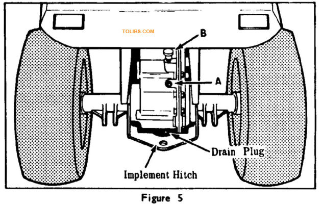
SINGLE POINT IMPLEMENT HITCH (See Fig. 5)
A fixed hitch is supplied as standard equipment for the towing of implements.
SEAT SAFETY SWITCH
A safety switch located in the seat stops the engine if the operator leaves the seat while the P.T.O. switch is “On”.
HOOD RELEASE (See Fig. 6)
Push in to release the hood, permitting access to the engine, battery, and gas tank.
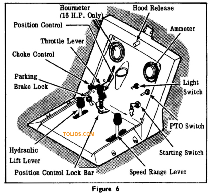
STARTING SWITCH AND KEYS (See Fig. 6)
Two keys are supplied with each tractor, taped to the starting switch. To start engine, insert key in switch, turn clockwise to “ON” position and release when engine starts. Do not hold key in “ON” position for more than 30 seconds at a time. Key should be removed when tractor is not in use to prevent unauthorized operation. See “Operating Instructions" for complete starting information.
FORWARD PEDAL (See Fig. 7)
Press the forward pedal down with the toe of your right foot for forward movement of the tractor.
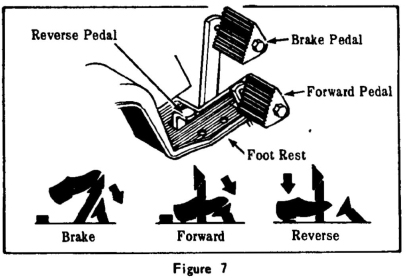
REVERSE PEDAL (See Fig. 7)
Press the reverse pedal down with your nght heel for reverse movement of the tractor.
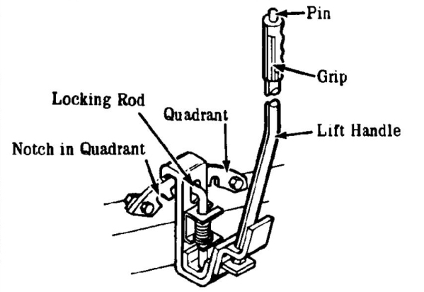
IMPLEMENT LIFT HANDLE (On 12 H.P. Tractor Only) (See Fig 8)
The lift handle is used to manually raise and lower the same implements as the Hydraulic Lift such as the snow thrower, trip dozer blade and rotary mower.
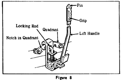
The lift handle can be locked in various positions. To place an implement in working position, push the pinon the handle downward and push forward until the locking rod catches the desired notch of the quadrant. To place in transport position, push the pin downward and pull the handle back until the locking rod catches in the rear notch. When mounting implements, place the handle in the forward position.
HYDRAULIC LIFT (On 14 & 16 H.P. Tractors Only) (See Fig. 6)
The Hydraulic Lift is used to raise and to lower implements used with the tractor. It can only be used with the engine running. Operate by pulling backward to raise, and pushing forward to lower. When the lever is released it will automatically return to the “LOCK” position.
SPEED RANGE LEVER (See Fig. 6)
The speed range lever is used in conjunction with the throttle control and the foot pedals to determine tractor operating speed. It has three positions "Low”, "Neutral” and “High”. “Low” range positions the transmission in a low gear ratio for Slower tractor speed and greater pulling force. "Neutral” disengages the gears. The speed range lever must be in “Neutral” to start the engine. "High” range positions the transmission in a high gear ratio for faster tractor speed and less pulling force.
POSITION CONTROL (On 14 & 16 H.P. Tractors Only) (See Fig. 6)
The position control is used to adjust the operating height of front attachments. Proper adjustment of the position control allows the implement to return to the same pre-set operating height each time it is lowered. The position control is intended primarily for the mower but can be used to obtain a similar adjustment for the dozer blade and snow thrower. Proceed as follows:
- Raise attachment.
- Loosen lock bar.
- Turn knob clockwise to lowest position.
- Lower attachment and adjust to desired height.
- Turn position control knob counterclockwise until lift is contacted (resistance is felt).
- Tighten the lock bar finger tight. Do not use a wrench.
POWER TAKE-OFF SWITCH (See Fig. 6)
The P.T.O. switch engages the engine drive pulleys to operate implements. It must be in the "OFF” position to start the engine. If the operator leaves the seat while the P.T.O. switch is “On”, the engine will stop (kill). Operating instructions, belt adjustments, etc., concerning the use of the power take-off with any implement are covered in the Operator’s Manual furnished with the implement.
NOTE: Check periodically to make sure the screw holding PTO clutch to engine shaft is tight.
OPERATING INSTRUCTIONS
PREPARING TRACTOR FOR OPERATION
The operating speed and throttle setting will be determined by the implement being used as well as individual conditions encountered in the work being performed. The Operator’s Manual supplied with each implement should be consulted for detailed operating instructions.
It is important to become thoroughly familiar with the handling characteristics of your tractor and with the instructions contained in this manual BEFORE attempting to use your tractor for the various operations which it can perform. Drive the tractor without operating an implement until you become familiar with its controls. Refer to the Maintenance and Lubrication sections in this Manual and perform the indicated operations prior to operating the tractor.
WEIGHT FOR ADDED TRACTION
Wheel weights are available as accessories for both front and rear wheels. These weights will increase the drawbar pull. The weight added by these accessories is as follows:
- Front Wheel Weights: 20 lbs, (9.07 kg.) each
- Rear Wheel Weights: 53 lbs. (24.4 kg.) each
Whether used on the front or rear of the tractor, wheel weights should be used in pairs, that is, one on each side. Operation with weight on one side only will cause uneven tire wear and will cant or tip the tractor, which can result in improper operation of certain implements.
Liquid fill can be used in the tires as an alternate or in addition to the wheel weights. The tires and tubes are equipped with a special inflation valve so they can be filled three-quarters full of liquid to provide additional weight. If the anticipated temperatures are below freezing, a calcium chloride solution should be used. After the tires have been three-quarters filled with liquid, compressed air is used to inflate them to the pressures recommended under “Tire Maintenance’’.
When checking inflation pressure of liquid-filled tires, turn the wheel so that valve stem is at the top to avoid getting fluid into the tire gauge.
IMPORTANT: If calcium chloride solution is used in the tires over an extended period of time, it is recommended that inner tubes be used. Such tubes can be obtained from most well stocked tires stores.
FRONT END LOADER
Standard front spindles are not suitable when the tractor is used with a front end loader. When using a front end loader, Hardened Front Spindle Service Kit No. JAC -500884 MUST BE USED.
OPERATING PROCEDURE
STARTING THE ENGINE
IMPORTANT
The engine will not start unless, the P.T.O. switch is in “Off” position and the speed range lever is in “Neutral”. The seat switch is located in the seat between the foam pad and the metal backing. It does not cover the entire seat. Therefore, it is possible to partially sit in the seat and not activate the switch, or to shift positions in the seat and interrupt the engine operation if the P.T.O. switch is “On”. If the engine fails to start, cheek to be sure that other switches and controls (shift lever) are in "Off” or “Neutral position.
- Open the fuel tank shut off valve.
- Sit in the operator’s seat.
- Put P.T.O. switch in “OFF" position.
- Engage the parking brake.
- Put speed range lever in "Neutral".
- Pull choke control back to fully close choke, and move throttle lever to “Fast” position.
- Insert starting key and turn it clockwise as far as possible until engine starts. DO NOT OPERATE STARTER FOR MORE THAN 30 SECONDS AT A TIME. If the engine does not start within this time, turn the key to “Off" position and wait for a minute or two before trying again.
- After engine starts, push choke control in halfway; then, when engine is properly wanned, push choke control in all the way to open choke.
STOPPING THE ENGINE
- Put P.T.O. switch in “OFF” position.
- Apply the brake to stop tractor motion.
- Place speed range lever in "Neutral”.
- Depress brake pedal and engage parking brake.
- Turn starting switch to “OFF” position.
- Remove the key if tractor is to be left unattended.
- Close the fuel tank shut-off valve if the tractor will not be operated for an extended period.
OPERATING HYDROSTATIC TRANSMISSION
Proper engine power is necessary for optimum tractor and implement operation. With a conventional transmission, the correct gear ratio and throttle setting is selected for the load and operating conditions encountered. Maximum pulling force is obtained in the low range ratio with the engine operating at full throttle. In the case of the hydrostatic transmission, maximum pulling force will occur at the slowest ground speeds, in low range and full throttle.
Thus, for any one throttle setting, depressing the foot control pedal reduces the tractor pulling force and increases tractor speed, a condition comparable to operating a conventional transmission tractor in a high gear ratio. With the speed range lever in the "Neutral” position and the P.T.O. clutch switch in the “OFF” position, start and operate the tractor as follows:
- Start the tractor engine and advance the throttle slightly.
- Disengage the parking brake.
- Select the speed range desired and move the lever accordingly.
- Advance the throttle setting to the desired rpm for the operation to be performed, and slowly depress the pedal.
- The correct tractor speed is a composite setting involving the throttle control, speed range lever and the hydro control pedals. However, for any one throttle and speed range setting, depress the foot pedal until the correct operating speed is obtained.
- If the tractor operates too slowly and the engine appears to be racing, apply more pressure to the foot pedal.
- If the tractor engine appears to be slowing down or“lugging” i.e., laboring under the tractor load, decrease the pressure on the foot pedal. This will increase the power to the rear wheels.
HILLSIDE OPERATING AND HILL CLIMBING
- Operators must use good judgement when operating on hillsides. They must consider the percent of slope and the condition of the turf (wet, firm, density, etc.). If tractor tends to slide when operating on an extreme hillside change the angle of the tractor by turning slightly downhill until traction is regained.
- Keep tires properly inflated. See "Maintenance”.
- When driving up hills, maintain full engine speed, but let up on treadle control. This will maintain the performance necessary.
BRAKE PEDAL ADJUSTMENT (See Fig. 9)
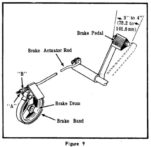
- Adjust the brake actuator rod so that the brake is applied (brake band is tight on brake drum) when the pedal has traveled approximately 3to4” (76.2 to 101.6 mm) from its norma] (released) position.
- To adjust the working length of the brake actuator rod, backoff lock nut “A” to free adjusting nut ”B”. Turn “B” counterclockwise, toward rear of tractor, to lenghten rod for more pedal travel or turn clockwise, toward front of tractor, to shorten rod for less pedal travel. Tighten lock nut "A” after brake has been adjusted.
IDLER ARM TENSION SPRING ADJUSTMENT
See your Rotary Mower Operator’s Manual for adjustment of the idler arm tension spring.