- Home
- Manuals
- MAN Trucks
- MAN TGS and TGX Workshop Manual
MAN TGS and TGX Workshop Manual

MAN TGS and TGX Workshop Service Repair Manual
Model number, vehicle identification number, vehicle number, basic vehicle number
The three-digit model number, also called model code, provides a technical identifi cation of the MAN chassis and also identifi es to which vehicle range it belongs. This number is part of the 17-digit vehicle identifi cation number (VIN) and is located at digits 4 to 6 in the VIN. The basic vehicle number, formulated for sales purposes, also contains the model number at digits 2 to 4. The seven-fi gure vehicle number describes the technical equipment on a vehicle; it contains the model number at digits 1 to 3, followed by a four-digit sequential number. The vehicle number is to be found in the vehicle papers and on the vehicle’s manufacturing plate.
The vehicle number can be quoted instead of the 17-digit vehicle identifi cation number in the event of any technical queries regarding conversions and bodies. Table 5 gives some examples of the model number, vehicle identifi cation number, basic vehicle number and vehicle number.
| Vehicle designation | Model number Model code |
Vehicle identifi cation number (VIN) |
Basic vehicle number |
Vehicle number |
| TGX 18.440 4x2 BLS TGS 26.410 6x2-4 LL TGX 33.540 6x4 BB |
06X 21S 26X |
WMA06XZZ97K001464 WMA21SZZ67M479579 WMA26XZZ67K001465 |
L06XKG31 L21SGF38 L26XLV12 |
06X0004 21S0002 26X0001 |
Use of logos
MAN logos on the chassis may not be removed or modifi ed in any way without prior approval from MAN. Modifi cations to the chassis or body that do not conform with this Guide to Fitting Bodies and that have not received MAN approval ba MAN (for address see “Publisher“ above) must receive a new vehicle identifi cation number (VIN) from the manufacturer responsible for the modifi cation (normally the vehicle conversion company). In such cases where the chassis/vehicle has received a new VIN, the logos on the radiator grille (MAN lettering, lion emblem) and the doors (door designation - see Section 2.1.1) must be removed.
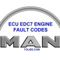
TGS and TGX cabs are of different sizes. There are 3 different cabs each:
Table 7.1: TGS cabs up to EURO 5 exhaust emission standard
Engine variants
In-line six-cylinder Diesel engines (R6) of the D20/D26 Common Rail range are installed in the TGS and TGX (= 1st – 3rd digits of the engine designation). The engines are available in Euro 4 with cooled EGR and PM-Kat® plus Euro 5 with SCR technology. A newly developed V8 Common Rail engine from the D28 family supplements the TGX range. In accordance with European regulations the engines are fi tted with on board diagnosis, including a NOx analyser (with engine torque limitation in the event of NOx analyser failure). and exhaust gas aftertreatment in accordance with the following table:
| EGR: | Exhaust Gas Recirculation |
| EEV: | Enhanced Environmentally friendly Vehicle |
| OBD: | On-Board Diagnostics |
| PM-Kat®: | Particulate Matter (particle fi lter) |
| SCR: | Selective Catalytic Reduction using “AdBlue” as the reducing agent |
National and international regulations take priority over technically permissible dimensions and weights if they limit the technically permissible dimensions and weights. The following data can be obtained from the quotation documents and documents contained in MANTED® at www.manted.de:
- Dimensions
- Weights
- Centre of gravity position for payload and body (minimum and maximum position for body)
for the production standard chassis / tractor unit. The data contained in these documents may vary depending on what technical features the vehicle is actually fi tted with upon delivery. The critical factor is the vehicle’s actual confi guration and condition at the time delivery. To achieve optimum payload carrying capability the chassis must be weighed before work starts on the body. Calculations can then be made to determine the best centre of gravity position for payload and body as well as the optimum body length. As a result of component tolerances the weight of the standard chassis is allowed to vary by ± 5%, in accordance with DIN 70020. Any deviations from the standard equipment level will have a greater or lesser effect on dimensions and weights. Changes in equipment may result in deviations in the dimensions and weights, particularly if different tyres are fi tted that then also lead to a change in the permissible loads.
Interchangeable containers
MAN swap body fi ttings: The TGS/TGX range includes fully air-sprung vehicles that can be supplied ex-factory with swap body fi ttings. Installation dimensions and centring devices correspond to the requirements of EN 284. There is a dedicated module in MANTED® where CAD drawings of the MAN swap body fi ttings can be viewed.
Container and interchangeable platforms that meet the requirements of EN 248 may be fi tted to the vehicles stated above. The standard swap body fi ttings cannot however be freely utilised if different bodies that do not meet the requirements of EN 248 are to be mounted. The relocation of support points or different dimensions are only permitted if they have been approved at MAN (for address, see ‘Publisher’ above). Do not remove the centre supports – their use is imperative!
The body must lie along their whole length. If this is not possible for design reasons, then an adequately dimensioned subframe must be fi tted. Supports for interchangeable containers are not suitable for absorbing forces that are exerted by mounted machinery and point loads. This means that when, for example, fi tting concrete mixers, tippers, fi fth-wheel subframes with fi fth-wheel couplings, etc, different fi xtures and supports must be used.
The body manufacturer must provide evidence that they are suitable for this purpose. Other interchangeable equipment: Interchangeable containers should lie on the upper side of the frame, along the whole length of the frame. A subframe can be omitted if the requirements in the following Section 5.4.5 „Self-supporting bodies without subframe“ are met. Frame longitudinal members must however, be protected from wear (e.g. by fi tting an anti-wear profi le as shown in Fig. 93). Materials with a yield point of σ0,2 ≤ 350 N/mm² may be used for the anti-wear profi le, but not for the subframe. The anti-wear profi le may assume the functions of a subframe only if it can be demonstrated by calculation that it is suitable for this purpose.
In each individual case when a body is fi tted care needs to be taken to ensure the following
- Under no circumstances may the permissible axle weights be exceeded
- A suffi cient minimum front axle load is achieved
- The position of the centre of gravity and loading must not be one-sided
- The permissible overhang (vehicle overhang) is not exceeded.
Axle overload, one-sided loading
- Fig. 1: Overloading the front axle ESC-452
- Fig. 2: Difference in wheel load ESC-126
This means for example that the wheel load on one side is 5,225 kg and 5,775 kg on the other. The calculated maximum wheel load provides no information on the permissible individual wheel load for the tyres fi tted. Information on this can be found in the technical manuals supplied by the tyre manufacturers.
Minimum front axle load
In order to maintain steerability, the stipulated minimum front axle load must be ensured under all vehicle load conditions, see table 12.
- Fig. 3: Minimum front axle loading ESC-451
Minimum front axle loading for any load condition as a % of the respective actual vehicle weight
Minimum front axle loading for any load condition as a % of the respective actual vehicle weight
GVW = Gross vehicle weight
SDAH = Rigid drawbar trailer
ZAA = ZAA = Centre-axle trailer
Wheels, rolling circumference
Different tyre sizes on the front and rear axle(s) can only be fitted to all-wheel-drive vehicles if the difference in rolling circumference of the tyres used does not exceed 2% or 1.5% if the MAN HydroDrive® system is installed. The basis for calculation is always the circumference of the smaller tyre. Every change of tyre type requires approval from the manufacturer. Enquiries can be made by completing the form “Request for certifi cation”, available to download from www.manted.de or via the online certifi cation form. Any associated parameterisation will be carried out at the same time as certifi cation.
The notes in Chapter 5 “Body” relating to anti-skid chains, load rating and clearance must be observed.
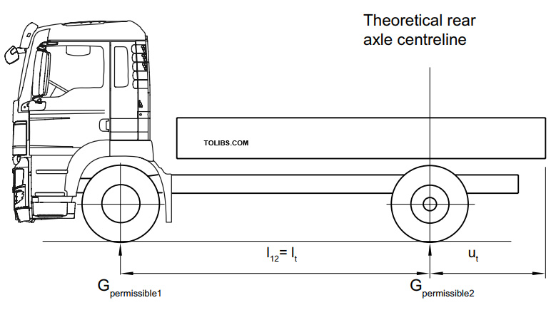
Permissible overhang
The permissible overhang length is defi ned as the distance between the theoretical rear axle centreline (resulting from the theoretical wheelbase) and the end of the vehicle (including the bodywork). For defi nition see the following the following paragraph 3.5. The following maximum values are permitted, expressed as a percentage of the theoretical wheelbase
- Two-axle vehicles 65%
- all other vehicles 70%.
If the vehicle is not equipped to tow trailers the above values may be exceeded by 5%. The basic requirement is that the minimum front axle loads given in table 12 (par. 3.2.) must be observed for every operating condition.
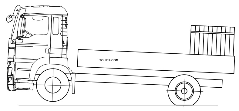
Theoretical wheelbase, overhang, theoretical axle centreline
The theoretical wheelbase is an aid for calculating the position of the centre of gravity and the axle loads. The defi nition is given in the following fi gures.
- Fig. 4: Theoretical wheelbase and overhang – two-axle vehicle ESC-446
- Theoretical wheelbase and overhang for a three-axle vehicle with two rear axles and identical rear axle loads ESC-447

Calculating the axle load and weighing procedure
It is essential that an axle load calculation be completed in order to ensure correct design of the body. The weights given in the sales documents only apply to production standard vehicles. Weight differences can be caused by optional equipment or manufacturing tolerances. Manufacturing inaccuracies (within tolerances) may occur. Achieving optimum compatibility between bodywork and truck is only possible if the vehicle is weighed before any work on the body is commenced. The weights thus obtained are then taken as a basis for an axle load calculation.
The vehicle must be weighed subject to following conditions:
- Without the driver
- With a fully fi lled AdBlue® tank and fully fi lled fuel tank
- With the handbrake released and the vehicle secured with chocks
- If fi tted with air suspension, raise the vehicle to normal driving position
- Liftable axle(s) must be raised to the normal driving position (as in loaded condition)
- Do not actuate any moving-off aid.
Checking and adjustment procedures before and after body has been fitted
On the TGS/TGX do not check or adjust:
- ALB settings: No adjustments necessary once bodywork has been fitted
- Tachograph ‘MTCO’ – as this has already been calibrated at the factory
- Digital tachograph ‘DTCO’ – as this has already been calibrated at the factory.
According to EU Directives however, a person authorised to carry out tests must enter the registration number (normally this is not yet assigned when the vehicle leaves the MAN factory). When installing a central lubrication system:
- Do not connect the lubrication system to the low-maintenance brake camshafts on drive axles fi tted with drum brakes.
- Drive axles fi tted with drum brakes are installed on all-wheel drive vehicles and on vehicles of medium build height (planetary axles).
- Low-maintenance brake camshafts can be recognised from their protective tube, see Fig. 8.
- Lubrication may only be applied every 4 years using special high-temperature grease in accordance with MAN Standard 284.
Checking and adjustment procedures that must be completed by the bodybuilder before/once the body has been fitted:
- Before the body is fitted, the roof spoiler supplied by MAN and mounted on the chassis frame must be fitted onto the cab roof.
- Basic beam alignment of the headlamps, see also Section 6.6 in this booklet for details
- Check battery charge status according to the charging schedule, sign battery charging log. See also the Chapter “Electrics, electronics, wiring”
- Check rear underride protection for compliance with statutory regulations.
- Check sideguards for compliance with statutory regulations (for dimensions see the Chapter “Modifying the chassis”) and adjust as necessary.
- A digital tachograph ‘DTCO’ must be calibrated after the body has been fi tted. Furtermore, all information e.g. vehicle registration number and the country of registration must be added. Since April 2011 the vehicle registration number and the country of registration must be entered into new tachographs using the company card, even if the calibration data is not changed. This must be performed by an authorised person.
Notes on MAN Hydrodrive®
MAN Hydrodrive®is a hydrostatic front axle drive that employs wheel hub motors. The system is selectable and operates in the speed range between 0 and 28 km/h. Vehicles fi tted with Hydrodrive®are legally regarded as off-road vehicles as defi ned by 70/156 EEC(as last amended by 2005/64/EU and 2005/66/EG). The Hydrodrive®hydraulic circuit is solely approved for the regulated drive of the front axle and may not be used to supply other hydraulic systems. Modifi cations to the Hydrodrive®hydraulic system (including relocating pipework) may only be carried out byspecifi cally authorised companies. In the case of semi-trailer tippers and other bodies where there is a risk of the cargo falling into the area around the oil cooler an oil cooler cover must be fi tted. This is available fi tted ex-works or as a retrofi t solution under the name ‚Protective cover for oil cooler/fan for HydroDrive®’. (Installation no. 81.36000.8134).
Modifying the chassis
To provide customers with the products they want, additional components sometimes need to be installed, attached or modifi ed.For uniformity of design and ease of maintenance, we recommend that original MAN components be used as long as these complywith the vehicle’s structural design. To keep maintenance work to a minimum, we recommend the use of components that have the same maintenance intervals as the MAN chassis. Modifi cations to safety-critical components of wheel/axle guides, steering and brakes are not allowed. Existing anti-roll bars may neither be removed nor modified.
Installation and/or modifi cation of components frequently requires intervention in the control unit’s CAN architecture (e.g. when extending the EBS electronic braking system). The necessary modifi cations and/or expansion of the vehicle programming are described under the corresponding topic in these guidelines. Such modifi cations may only be undertaken with assistance from the electronics experts at MAN service centres and the programming must be approved by MAN (for address see “Publisher” above). Retrofi tted systems may, under certain circumstances, not be assimila-ted into the vehicles’ on-board Trucknology®systems “Time maintenance system” of “Flexible maintenance system”. For this reason it is not possible to achieve the same degree of maintenance convenience as is possible with original equipment.
Corrosion protection
Surface and corrosion protection affects the service life and appearance of the product. In general, the quality of the coatings on body components should be equal to that of the chassis.
In order to fulfi l this requirement, theMAN Works Standard M 3297 “Corrosion protection and coating systems for non-MAN bodies”is binding for bodies that are ordered by MAN. If the customer commissions the body, this standard becomes a recommendation only. Should the standard not be observed, MAN provides no guarantee for any consequences. MAN-works standards may be sourced via www.normen.man-nutzfahrzeuge.de, registration required. For corrosion protection of the body see chapter 5.2.
Series production MAN chassis are coated with environmentally friendly, water-based 2-component chassis top-coat paints at approx.80°C. To guarantee uniform coating, the following coating structure is required for all metal component assemblies on the bodyand subframe:
- Bare metal or blasted component surface (SA 2.5)
- Primer coat: 2-component epoxy primer, permitted in accordance with MAN standard M 3162-C if possible,cathodic dip painting to MAN works standard M 3078-2,
with zinc phosphate pre-treatment - Top coat: 2-component top-coat paint to MAN works standard M 3094, preferably water-based; if there are nofacilities for this, then solvent-based paint is also permitted. (www.normen.man-nutzfahrzeuge.de, registration required).
See the relevant paint manufacturer’s data sheets for information on tolerances for drying and curing times and temperatures. When selecting and combining materials the compatibility of the different metals (e.g. aluminium and steel) must be taken into consideration as must the effects of the ‘electrochemical series’ (cause of contact corrosion).
After all work on the chassis has been completed:
- Remove any drilling swarf
- Remove burrs from the edges
- Apply wax preservative to any cavities
Mechanical connections (e.g. bolts, nuts, washers, pins) that have not been painted over must be given optimum corrosion protection.To prevent the occurrence of salt corrosion whilst the vehicle is stationary during the body-building phase, all chassis must be washed with clean water to remove any salt residues as soon as they arrive at the body manufacturer’s premises.
Drill holes, riveted joints and screw connections on the frame
If possible, use the holes already drilled in the frame. No drilling should be carried out in the fl anges of the longitudinal frame member profi les, i.e. in the upper and lower fl anges (see Fig. 10). The only exception to this is at the rear end of the frame, outside the area of all the parts fi tted to the frame that have a load-bearing function for the rearmost axle (see Fig. 11). This also applies to the subframe.