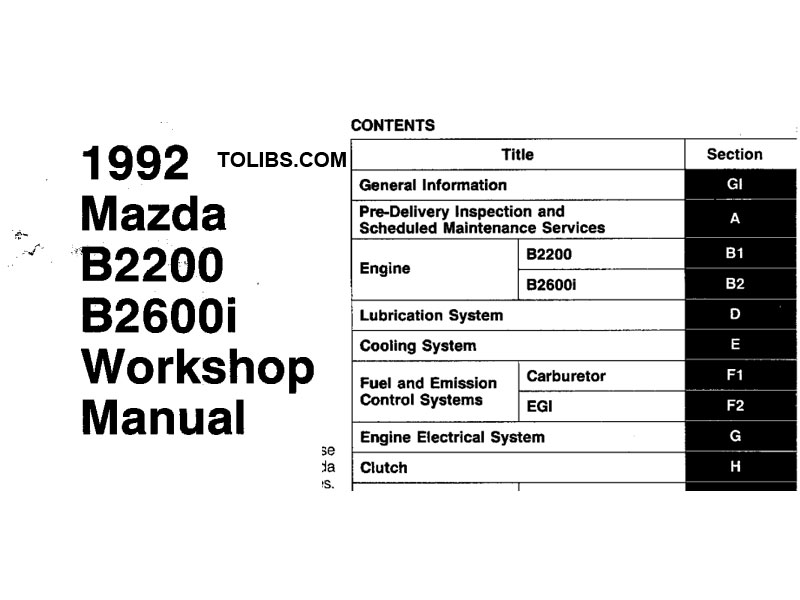
1992 Mazda B2200, B2600i Workshop Manual
Mazda B2200 and B2600i Repair Manual
REPAIR PROCEDURE
- Most repair operations begin with an overview illustration. It identifies the components, shows how the parts fit together, and visual parts inspections. If a damaged or worn part is found, repair or replace it as necessary.
- Expendable parts, tightening torques, and symbols for oil, grease, and sealant are shown in the overview illustration.
- Pages related to service procedures are shown under the illustration. Refer to this information when servicing the related part.
This workshop manual is intended for use by service technicians of Authorized Mazda Dealers to help them service Mazda vehicles. For proper repair and maintenance, a thorough familiarization with this manual is important, and it should always be kept in a handy place for quick and easy reference.
All the contents of this manual, including drawings and specifications, are the latest available at the time of printing. As modifications affecting repair or maintenance occur, relevant information supplementary to this volume will be made available at Mazda dealers. This manual should be kept up-to-date.
VEHICLE IDENTIFICATION NUMBERS (VIN)
- JM2UF123*NO 250001
- JM2UF223* NO 250001
- JM2UF323 *NO 250001
- JM2UF113*NO 250001
- JM2UF213*NO 250001
- JM2UF313*NO 250001
- JM2UF114*NO 250001
- JM2UF314*NO 250001
- JM2UF414*NO 250001
- JM2UF614*NO 250001
- JM2UF514*NO 250001
- JM2UF223*NO 250001
VACUUM CONTROL VALVE SYSTEM, AIR CLEANER
This system prevents fuel from overflowing into the carburetor from the float chamber. While the engine is being driven at full throttle, the float chamber temperature becomes high and may cause fuel in the chamber to bubble and force its way out through the air vent tube and into the carburetor air stream. The VCV system controls float chamber pressure to prevent this bubbling. The vacuum control valve opens the passage from the float chamber to the intake manifold according to secondary venturi vacuum.
VACUUM CONTROL VALVE
Inspection
- Remove all the hoses from the vacuum control valve.
- Connect a vacuum pump to No.1 port.
- Operate the vacuum pump, and verify that the passage between the No.2 and No.3 ports opens as specified.
Specification: 40 mmHg (1.57 inHg) or more
AIR CLEANER ELEMENT
Inspection
- Remove the air cleaner element.
- Blow out the dust with compressed air.
- Install the air cleaner element.
POSITIVE CRANKCASE VENTILATION (PCV) SYSTEM
This system reburns the combustion blowby gases. The system consists of tile PCV valve, which operates while the engine is running to control the flow of blowby gases according to intake manifold vacuum.
PCV VALVE
Inspection
- Warm up the engine and run it at idle.
- Disconnect the PCV valve together with the ventilation hose from the cylinder head cover.
- Block the PCV valve opening with a finger, and verify that the engine speed drops.
HOT-IDLE COMPENSATION SYSTEM, ACCELERATOR CABLE
This system supples secondary air into the intake manifold to stabilize idle speed when air intake temperature is more than 67°C (153°F).
IDLE COMPENSATOR
Inspection
- Verify that the valve is in closed position when the bimetal temperature is less than specified. Opening temperature: 63-71°C (145-160°F)
- With the valve closed, suck air through the hose. If excessive air leakage is found, replace the idle compensator as an assembly.
- When the bimetal temperature is higher than approximately 71°C (160°F), verify that the valve is open. If it is not, replace the idle compensator as an assembly.
ACCELERATOR CABLE
Inspection
Note: Verify that the choke valve is fully open and that the throttle valve is set to the correct idle opening.
- Inspect the cable deflection at the carburetor.If it is not within 1-3mm (0.04-0.12 in), adjust by turning nuts A.
- Depress the accelerator pedal to the floor and verify that the throttle valve is fully open. Adjust by using bolt B, if necessary.
ALTITUDE COMPENSATION SYSTEM
This system increases the amount of air to the carburetor to prevent overrich air/fuel ratio at high altitudes. The system consists of the high-altitude compensator and carburetor. The high-altitude compensator provides additional air bleeds for the primary main and secondary main fuel circuits and supplies additional air into the intake manifold.