Mazda 929 .121 WORKSHOP MANUAL (Engine)
1975 Mazda 929 WORKSHOP MANUAL ENGINE. SUPPLEMENT
FOREWORD
This workshop manual was prepared as reference material for the service personnel of authorized Mazda dealers to enable them to correctly carry out the task of rendering services and maintenance on Mazda vehicles. In order to ensure that the customers are satisfied with Mazda products, proper servicing and maintenance must be provided. For this purpose, the service personnel must fully understand the contents of this workshop manual and at the same time, are recommended to keep the manual in a place where reference can readily be made.
This manual is a supplement to the 929 (ENGINE) workshop manual. Service information contained in this manual covers only those features that are new for 1975 929 (ENGINE). Refer to the 929 (ENGINE) workshop manual for service procedures common to previous and 1975 models.
This model is mounted with a 1,769 cc (107.9 cu-in) in-line water cooled, over head camshaft four cylinder engine. Its bore and stroke is 80 x 88 mm (3.15 x 3.46 in) and the compression ratio is 8.6 : 1.
COOLING SYSTEM
Expansion Tank
The shapes of the radiator, radiator cap, expansion tank, etc. have been changed as shown in Fig. 1 (Refer to Service Bulletin No. 408).
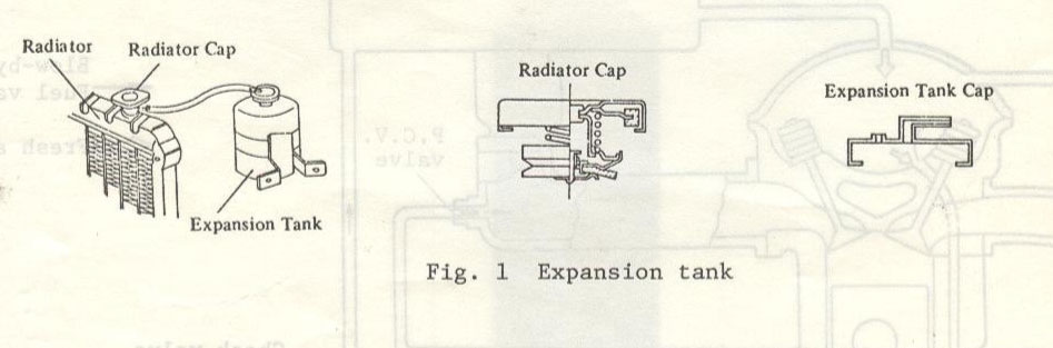
Note: Fill the coolant full in the radiator and between "F" and "L" marks in the expansion tank.
| Models | Car Nos. | Production Dates |
| Sedan | No. 128875 | Feb. 12, 1974 |
| Wagon | No. 109377 | Feb. 15, 1974 |
Fuel Pump
The fitting position of fuel pump has been changed from the inside of trunk room to the lower part of rear floor (Refer to Service Bulletin No. 448).
| Models | Car Nos. | Production Dates |
| Sedan | No. 137708 | Apr. 16, 1974 |
| Wagon | No. 111479 | Apr. 18, 1974 |
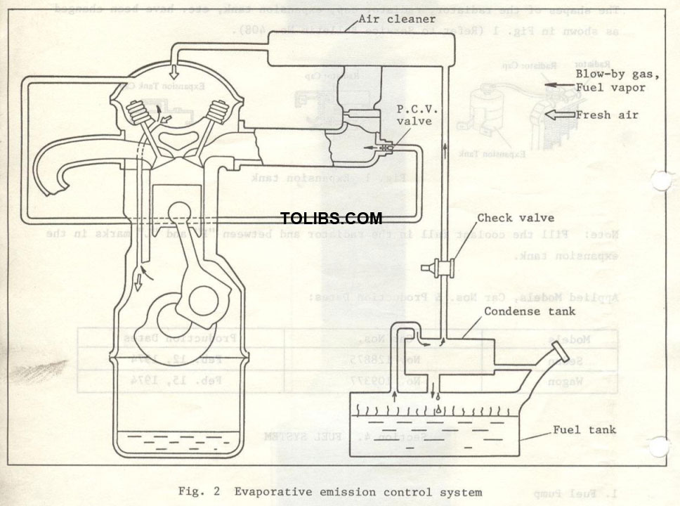
Evaporative Emission Control System (Australia only) The evaporative emission control system is newly equipped on 1975 year model.
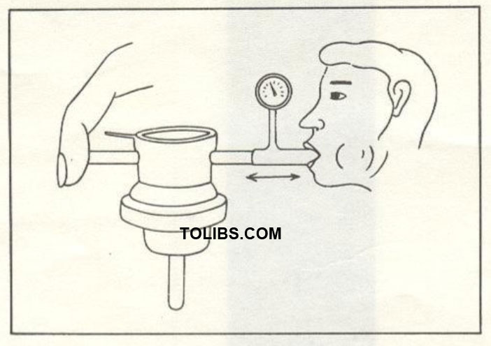
Checking check valve
- Remove the check valve.
- Install the pressure gauge at the one end of the check valve and blind the other end by finger.
Breath-out the check valve with the pressure of more than 0.04 kg/cm2 (0.57 lb/in) and breath-in with the negative pressure of more than 0.01 kg/cm2 (0.14 lb/in2). If the valve does not operate, replace it with a new one.
CHECKING COMPRESSION PRESSURE
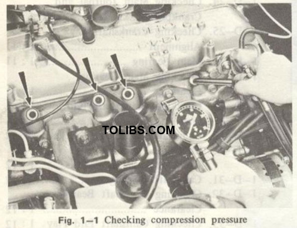
To check the compression pressure, proceed as fol lows:
- Be sure the engine oil is at the proper level and the battery is properly charged.
- Warm up the engine to the normal operating temperature.
- Remove all spark plugs.
- Set the throttle valve to the wide open position.
- Race a compression gauge in the spark plug hole.
- Crank the engine with the starting motor until the pressure reaches a maximum value.
- Test the remaining cylinders in the same manner.
- The indicated compression pressures are considered normal if the lowest reading cylinder is within 75 percent of the highest.
If one or more cylinders read low, test the compression pressure again after pouring a small quantity of oil into each cylinder.
- If the compression pressure improves considerably, the piston rings or cylinder bores are worn.
- If the compression pressure does not improve, valves are sticking or seating poorly.
- If two adjacent cylinders indicate low compression pressures and pouring oil on the pistons does not increase the compression, the cause may be the cylinder head gasket leak between cylinders. Engine oil and/or coolant in the cylinders could result from this problem.
ENGINE REMOVAL
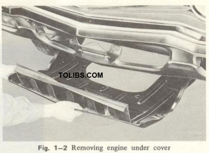
The procedures for removing the engine from the vehicle for overhauling are as follows:
- Remove the bonnet.
- Remove the engine under cover.
- Drain the cooling water by opening the drain cocks
- at the lower part of the radiator and right rear of the cylinder block.
- Drain the engine oil.
- Disconnect the negative cable at the battery.
- Pull off the primary wire and the high tension cable at the distributor.
- Disconnect the wire at the “B” terminal of the alternator and pull off the wiring coupler from the alternator.
- Disconnect the wire at the oil pressure switch.
- Remove the engine earth wire.
- Disconnect the wiring coupler in front of the cylinder head.
- Remove the upper and lower radiator hoses.
- Remove the bolts attaching the radiator cowling to the radiator.
- Remove the radiator attaching bolts and remove the radiator and cowling.
- Remove the hot air hose.
- Pull off the breather pipe from the rocker arm cover.
- Remove the bolts attaching the air cleaner body and remove the air cleaner assembly.
- Disconnect the throttle linkage at the carburetor and remove it from the valve rocker cover.
- Disconnect the choke wire from the carburetor.
- Disconnect the fuel pipe and fuel return pipe (if equipped) at the carburetor.
- Disconnect the vacuum pipe for power brake unit from the inlet manifold.
- Loosen the hose bands and disconnect the heater hoses from the inlet manifold fittings.
- Pull off the wires from the water temperature gauge unit and the carburetor solenoid.
- Disconnect the wires from the starting motor and remove the starting motor.
- Disconnect the exhaust pipe from the exhaust manifold.
- Remove the clutch cover plate and stays.
- Remove the nuts and bolts supporting the transmission to the engine.
- Support the transmission with a suitable jack.
- Remove the nuts and bolts from the right and left engien mountings.
- Install a suitable lifting sling on the engine hanger bracketAttach the sling to a hoist or other lifting device and take up all slack.
- Pull the engine forward until it clears the clutch shaft. Then, lift the engine from the vehicle.
- Remove the engine mounting brackets from the cylinder block and mount the engine on the engine stand (49 0107 680A or 49 0839 000 and 49 0221 005A).
ENGINE DISASSEMBLY
Engine overhaul should be done in the following order after removing the engine from the vehicle. If the engine repair stand is not available, take care so as to sufficiently protect the engine and its parts against damage.
See aslo Mazda 929 1991 Wiring Diagram Documaent.
Removing Distributor
- Disconnect the high tension cables from each spark plug.
- Pull off the vacuum control tube from the distributor.
- Remove the distributor locking nut and remove the distributor from the cylinder head.
Removing Exhaust Manifold
- Remove the bolts attaching the heat insulator to the exhaust manifold and remove the heat insulator.
- Remove the nuts attaching the exhaust manifold to the cylinder head and remove the exhaust manifold and gaskets.
Removing Alternator
- Remove the alternator strap attaching bolt.
- Remove the alternator mounting bolts and remove the alternator and the “V” belt.
Removing Oil Filter
- Remove the oil filter cartridge with the wrench (49 0223 195).
- Remove the bolts attaching the filter cover to the cylinder block and remove the filter cover and gasket.
Removing Cooling Fan and Pulley
- Remove the bolts that attach the cooling fan and pulley to the water pump boss.
- Remove the cooling fan, spacer and pulley.
Removing Water Pump
- Loosen the hose band and disconnect the water bypass hose (water pump ~ inlet manifold) from the inlet manifold.
- Disconnect the water bypass hose (water pump thermostat case) from the thermostat case.
- Remove the nuts and bolts that attach the water pump to the timing chain cover.
- Remove the water pump and alternator strap.
Removing Inlet Manifold and Carburetor Assembly
- Disconnect the vacuum tube (distributor - carbu retor) at the carburetor.
- Disconnect the hose (ventilation valve - oil separator) at the ventilation valve, if equipped.
- Remove the bolts attaching the inlet manifold to the cylinder head and remove the inlet manifold and carburetor assembly.
Removing Cylinder Head
Remove the attaching nuts and remove the valve rocker arm cover and gasket.
- Remove two semicircular oil seals.
- Install the ring gear brake (49 0221 030A) to the lywheel.
- Remove the lock nut and washer and slide the distributor drive gear off the camshaft.
- With the spanner (49 0164 631A) loosen the lock nut holding the camshaft sprocket.
ENGINE INSPECTION AND REPAIR
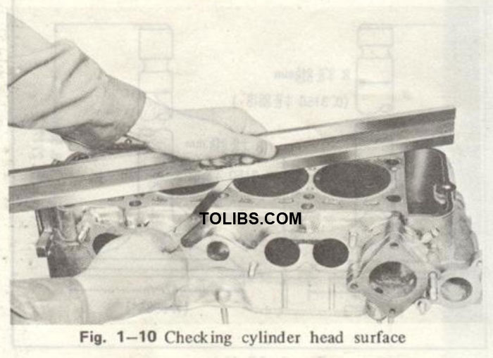
Cylinder Head Inspection
Remove all carbon in the combustion chamber and exhaust port. Be sure that the water passages are open. Inspect the tapped openings. Repair or replace any damaged threads or broken studs. Check for cylinder head distortion by placing a straight edge on the cylinder head surface. Measure the clearance between the straight edge and the cylinder head surface with a feeler gauge as shown in Fig. 1—10. If the distortion exceeds 0.15 mm (0.006 in), grind with a surface grinder.
Manifold Inspection
Check the intake and exhaust manifold for distortion. To check, place the manifold on a surface plate and check the clearance between the manifold and surface plate with a feeler gauge. If excessive distortion is found, correct it by grinding.
Valve Spring Inspection
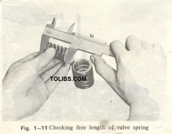
Examine the springs for corrosion or any damage. If it is severe, replace with new ones. Measure the free length and the fitting pressure. Replace with new springs if the free length is decreased under 36.2 mm (1.425 in) on the outer spring and 35.7 mm (1.406 in) on the inner spring, or if the fitting load is reduced under 10.4 kg (22.9 lb) on the outer spring and 6.3 kg (13.9 lb) on the inner spring.
The specifications of the springs are as follows:
| Inner spring | Outer spring | |
| Free length | 36.8 mm (1.449 in) | 37.3 mm (1.469 in) |
| Fitting length | 33.0 mm (1.299 in) | 34.5 mm (1.358 in) |
| Fitting load | 7.4 kg (16.3 lb) | 12.2 kg (26.9 in) |
Checking Valve Stem to Guide Clearance
The standard clearance between the valve stem and guide is, under the condition of the guide being fitted with the cylinder head, 0.018 - 0.053 mm (0.0007 - 0.0021 in) on the inlet side and 0.018 - 0.058 mm (0.0007 - 0.0023 in) on the exhaust side.
To check this clearance, place the valve in each guide. Check the clearance with a suitably mounted dial indicator, or feel the clearance by moving the stem back and forth. If the clearance is 0.20 mm (0.008 in) or more, replace the valve guide and valve.
Replacing Valve Guide
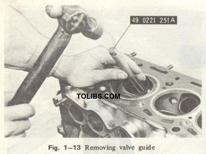
- Press out the old guide with the valve guide remover (49 0221 251A), as shown in Fig. 1-13.
Press in the new guide squarely with the same tool until the ring on the guide touches the cylinder head.
Inspecting and Refacing Valve Seat
Inspect the valve seats for cracks, burrs, ridges or improper angle and width. If necessary to reface the valve seats, use a valve seat grinder or valve seat cutter and grind to a 90 degree angle. Do not grind any more than is necessary to clean up the valve seat.