1978 Mazda Cosmo Service Workshop Manual

1978 Mazda Cosmo RX-4 RX-3SP Workshop Manual
FORWARD
The main service points on COSMO, RX-4 and RX-3SP that differ between 1977 and 1978 models are fully explained in this book as a guide for service personal of the Mazda family until the 1978 workshop manual will be supplied to you after several months. During that period, it is requested to refer to the other service points, safety notice and general service instructions in service shown in the 1977 workshop manual.
As all informations in this book are the best available at the time of printing, all alternations related to modifications will be notified by Service Informations. Toyo Kogyo reserves right to make changes in design and specifications without previous notice.
CHAIN ADJUSTER
The chain adjuster and its attaching stud bolts of the oil pump drive chain have been abolished.
INSPECTION CHAIN ADJUSTER
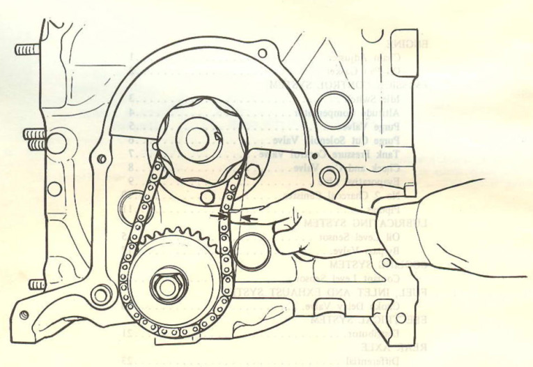
- Remove the oil pan.
- Remove the eccentric shaft pulley and front cover.
- Check the slack of the oil pump drive chain by pressing with a finger.
If the slack exceeds 13 mm (0.51 in), replace the drive chain with a new one.
OIL PAN GASKET
When installing the oil pan to the engine, both the gasket and the sealer must be used whether the engine is ON THE CAR or OFF THE CAR to prevent the oil leakage.
REMOVAL AND INSTRATION THE OIL PAN GASKET
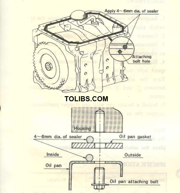
- Remove the oil pan attaching bolts and remove the oil pan with a suitable drift.
- Clean the mounting surfaces of oil pan and housings.
- Apply the 4 ~ 6 mm (0.16 ~ 0.24 in) diameter continuous bead of sealer to mounting surface of oil pan and place the gasket on it. The both ends of the bead should be overlapped.
- Apply the sealer onto the gasket as instructed in above.
- Install the oil pan and gasket assembly in position.
- Install the oil pan attaching bolts and tighten the bolts little by little in turn until the torque becomes 0.7 ~ 1.0 m-kg (5 ~ 7 ft-lb) evenly.
- Fill the oil in the engine.
- Operate the engine and check to see the oil is not leaking from the joining faces of the oil pan.
Sealer part number: 8527 77 739
IDLE SWITCH
The limiter cap (plastic cap) has been newly adopted on the idle switch adjusting screw.
ADJUSTMENT IDLE SWITCH
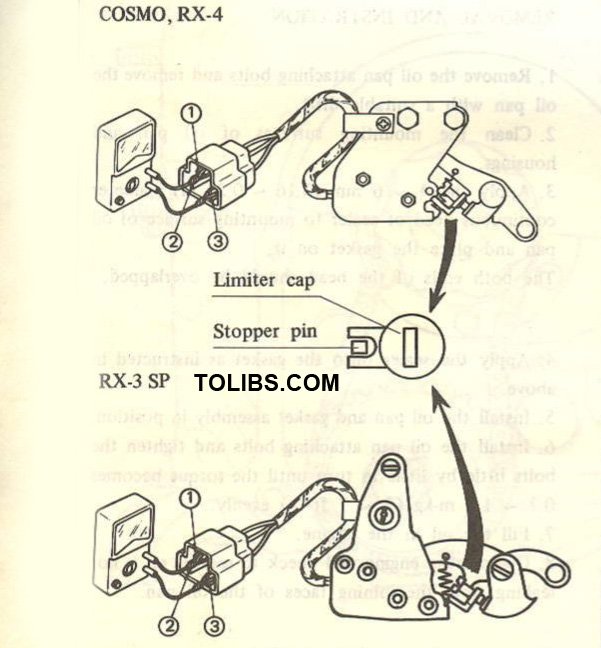
- Remove the limiter cap ( plastic cap) from the idle switch adjusting screw.
- Connect a tachometer to the engine.
- Disconnect the coupler of idle switch and connect an ohmmeter to (T) and (3) terminals in the coupler.
- Start the engine and slowly increase the engine speed with throttle. Turn the adjusting screw so that the continuity between (1) and (3) terminals does not exist at specification.
- Install a limiter cap with cap stopper positioned at stopper pin as shown in figure.
Note:
On the vehicle equipped with automatic transmission, place the selector lever in "N" position.
| Numbers-Continuity | Numbers-No continuity | Remarks |
| 1-3 | 1-2 | Run the engine at idle. |
| 1-2 | 1-3 | On the manual transmission, increase the engine speed up to 1,000 ± 50 rpm with throttle. |
| 1-2 | 1-3 | On the automatic transmission, increase the engine speed up to 1,200 ± 50 rpm with throttle in “N” range. |
ALTITUDE COMPENSATOR
The altitude compensator has been newly adopted on the inlet manifold.
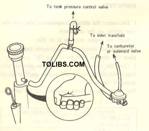
INSPECTION ALTITUDE COMPENSATOR
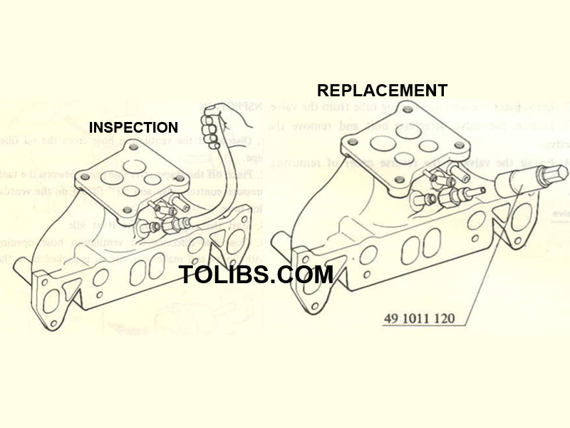
- Disconnect the altitude compensator hose from the hose fitting on the carburetor.
- Start the engine and run it at idle. On the vehicle equipped with automatic transmission, place the selector lever to “N” or “P” position.
- Close the altitude compensator hose opening with finger and check to see the engine speed drops as shown in the table.
| Altitude | Drops of idle speed |
| 0 -1,000 m (0-3,280 ft) |
10-100 rpm |
| 1,000 - 2,000 m (3,280-6,560 ft) |
50 - 200 rpm |
| More than 2,000 m (6,500 ft) |
More than 100 rpm |
REPLACEMENT
- Remove the air cleaner.
- Disconnect the hose from the altitude compensator.
- Remove the altitude compensator with the remover (49 1011 120).
- Install the altitude compensator in the reverse order of removing.
PURGE VALVE
The purge valve has been newly adopted on the crankcase and evaporative emission control system.
INSPECTION PURGE VALVE
- Disconnect the ventilation hose from the oil filler pipe.
- Pinch off the evaporative line hose between the tank pressure control valve and “T” fitting on the ventilation hose.
- Start the engine and run it at idle.
- Close the disconnected ventilation hose opening eith the finger and make sure the air is sucked in to the hose.
REPLACEMENT PURGE VALVE
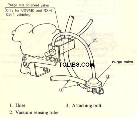
1. Disconnect the hoses from the purge valve.
2. Disconnect the vacuum sensing tube from the valve.
3. Loosen the valve attaching bolt and remove the valve.
4. Install the valve in the reverse order of removing.
PURGE CUT SOLENOID VALVE
The purge cut solenoid valve has been newly adopted.
INSPECTION PURGE CUT SOLENOID VALVE
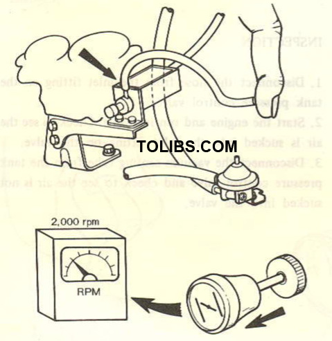
- Connect a tachometer.
- Start the engine and set the engine speed to 2,000 rpm with throttle.
- Disconnect the vacuum sensing tube from the purge valve and check to see the vacuum is sucked into the vacuum tube.
- Set the engine speed to 2,000 rpm with choke knob and check to see the vacuum is not sucked into the tube.
TANK PRESSURE CONTROL VALVE
The tank pressure control valve has been newly adopted on the evaporative control system.
INSPECTION TANK PRESSURE CONTROL VALVE
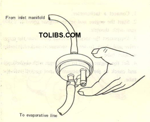
- Disconnect the hose from the inlet fitting on the tank pressure control valve.
- Start the engine and run it at idle. Check to see the air is sucked into the inlet fitting on the valve.
- Disconnect the vacuum sensing tube from the tank pressure control valve and check to see the air is not sucked into the valve.
REPLACEMENT TANK PRESSURE CONTROL VALVE
- Disconnect the hoses from the tank pressure control valve.
- Disconnect the vacuum sensing tube from the valve.
- Loosen the valve attaching bolt and remove the valve.
- Install the valve in the reverse order of removing.
CHECK AND CUT VALVE
The operating pressure of the check and cut valve, and the shape have been changed.
CHECK AND CUT VALVE INSPECTION
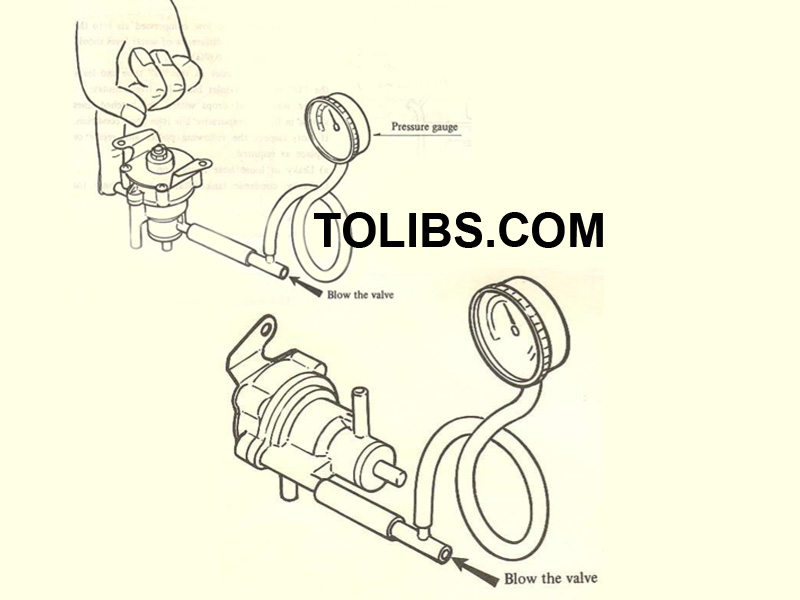
- Remove the check and cut valve.
- Connect a pressure gauge to the passage to the fuel tank or condense tank for station wagon and blind the other end by finger.
- Blow through the valve. The valve should open with the pressure of more than 0.055 - 0.07 kg/cm2 (0.78 - 1.0 lb/in2).
- Remove the pressure gauge and connect it to the passage to atomosphere.
- Blow through the valve and if the valve opens with the pressure of more than 0.01 - 0.05 kg/cm2 (0.14 - 0.71 lb/in2), the valve is normal.
Note: The test should be performed with the valve located horizontally. Otherwise the weight of the valve will move out of the position and cut the line.
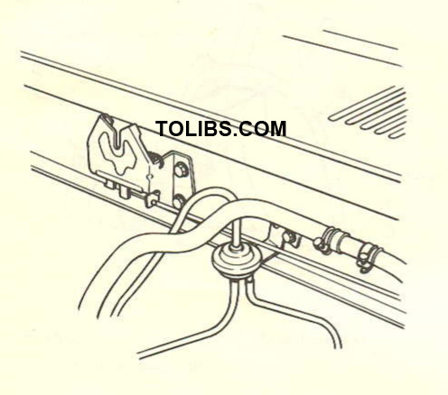
EVAPORATIVE LINE
The inspecting procedure of the evaporative line has been changed.
INSPECTION EVAPORATIVE LINE
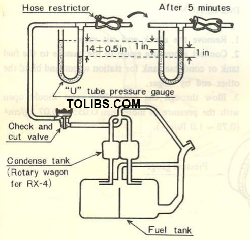
- Disconnect the evaporative hose from the tank pressure control valve.
- Connect the “U” tube pressure gauge to discon nected ventilation hose.
- Gradually apply the low compressed air into the “U” tube so that the difference of water level should be 356 + 12 mm (14 + 0.5 in).
- Then, blind the inlet of the “U” tube and leave the “U” tube with inlet blind for five minutes.
If the water level drops within the hatched lines shown in figure, evaporative line is in good condition. If not, inspect the following points and repair or replace as required.
- Leaky or loose hose connection
- Leaky condense tank (Station wagon only for RX-4)
- Leaky fuel tank
- Leaky or loose fuel line
- e) Leaky filler cap