Mazda RX-7 Competition Preparation and Service Manual

MAZDA RX-7 Workshop Manual and Wiring Diagrams
Toyo Kogyo Co., Ltd., wishes to extend appreciation for your interest in and efforts with the Mazda RX-7 in automobile competition. This Manual reflects the knowledge gained by Mazda competitors and Toyo Kogyo engineers through much research, development and actual competition, and is to be considered recommended practice. It is intended for use only by those seriously engaged in the construction and maintenance of the RX-7 in competition; the parts, procedures and specifications outlined within the Manual are for racing and competition use only, and specifically have no relation to or application or other purpose for street and highway-driven automobiles. If the information contained in this Manual is applied to a street or highway-driven RX-7, the results may include voided warranties, reduced reliability, and losses in performance, economy and emissions, all or some of which may be illegal in certain areas and which are definitely not approved by Toyo Kogyo Co., Ltd.
With the parts, procedures and specifications in the Manual the competitor can assemble and maintain the engine, drivetrain and chassis components and the various appropriate subsystems involved in a competition Mazda RX-7. The individual competitor should be aware that many of the parts and procedures outlined in this Manual may not be allowed under the rules and regulations of certain competition organizations, and it is the responsibility of the competitor, racer, mechanic or other person associated with racing a Mazda to have a full understanding of the pertinent rules and regulations of his competition governing body. For instance, the reader will notice there is no section in this Manual on the design and construction of a roll cage structure, as these details and requirements vary with different sanctioning organizations.
In competition there is a high degree of experimentation, and the reader is assumed to understand that such experimentation is on an individual basis, is not covered by this Manual, and from the position of Toyo Kogyo Co., Ltd., and its affiliates, is therefore categorized as non-recommended practice. Toyo Kogyo Co., Ltd. is interested in the results of any competition experimentation or experience, but specifically cannot recommend a new procedure until it has undergone a thorough analysis by appropriate company engineering staff.
In any form of automobile competition the individual is also considered to assume responsibility for his or her actions, and to realize and accept that automobile competition is, by its very nature, a hazardous activity with a high degree of risk of damage to equipment and/or personal injury. By the application of this Manual it is assumed the individual will be operating a competition automobile at or near the outer limits of its performance envelope, and the closer to those limits the greater the risk. Neither Toyo Kogyo Co., Ltd., nor any of their affiliates or employees assume any responsibility in any manner for any losses, either to equipment or persons, resulting from the use of any Mazda automobiles in competition or the application of any parts, procedures or specifications outlined in this Manual.
Finally, automobile competition is a constantly changing area of endeavor, subject to new technology, and this Manual is the current best recommended practice but is subject to change, without notice, at any time. Again, thank you for your interest in the Mazda RX-7 in automobile competition, and we extend you good luck and best wishes in your efforts.
| Type | 12A Rotary |
| Displacement, per rotor | 573 cc |
| Displacement, total | 1146 cc |
| Compression ratio | 9.4:1 |
| Intake porting | Peripheral |
| Exhaust porting | Peripheral |
| Carburetion | Twin throat, down draft Weber |
| Lubrication | Wet sump |
| Cooling | Liquid |
| Ignition | Transistorized, capacitive discharge (CDI) |
| Maximum allowable engine speed | 9,000 RPM |
Explanation and Description of Competition Parts.
A. Housing group.
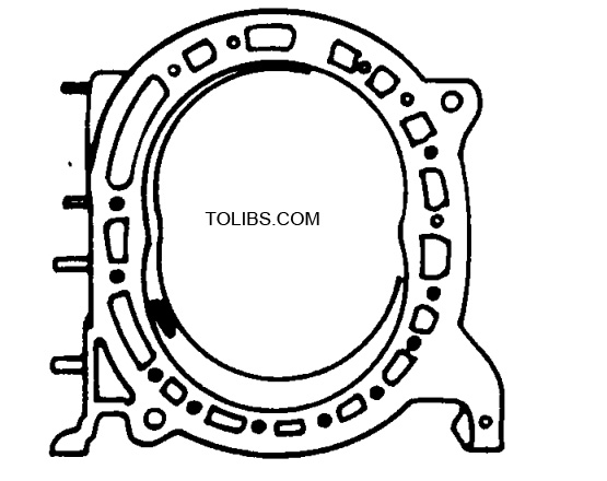
1. Rotor housing, 4352 10 100 It has the following differences from the stock housing:
- The intake porting is peripheral.
- It is sand cast from lower volume patterns.
- The coolant passages are different.
- The trochoid surface is directly chrome plated onto the casting instead of being a sheet metal insert.
The intake and exhaust timing is as follows:
Intake:
Opens 86° BTDC
Closes 75° ABDC
Exhaust:
Opens 73° BBDC
Closes 65° ATDC
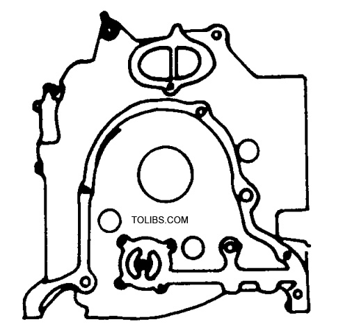
2. Side housings, front: 4352 10 200 intermediate: 4352 10 400 rear: 4801 10 300
They differ from the stock housings in these ways:
- The intake ports are filled in solid.
- The intermediate housing has an oil separator tank.
- The passages for the oil pump on the front housing are larger passages.
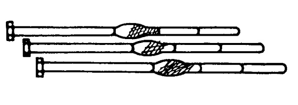
3. Tension bolts, 4352 10 451A These are the stock bolts with rubber bonded to them which dampens out vibrations at certain frequencies and prolongs bolt life.
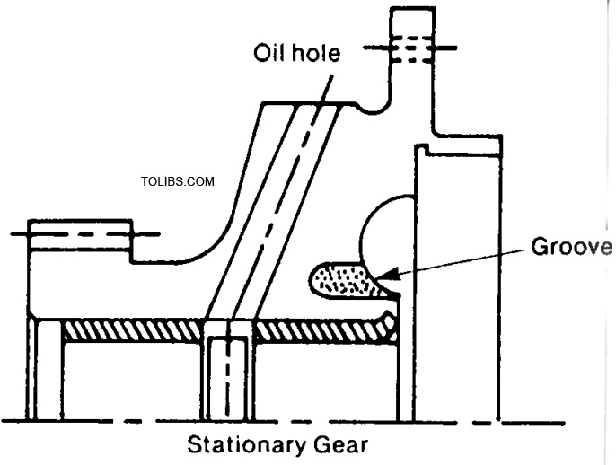
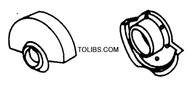
4. Stationary gears, front: 4352 10 500 rear: 435210 550 Compared to the stock gears, these have the following differences:
- For strength, the material and heat treatment is different.
- A machined groove around the bearing, this feature enhances bearing life.
5. Oil pan, 4352 10 700 This is an increased capacity pan to maintain pressure under racing conditions, particularly while cornering.
6. Baffle plate, 4352 10 709 This baffle plate will maintain an adequate oil supply around the oil pump pickup while cornering or braking.
B. Rotating group.
1. Balancer assembly, 4352 11 010 These pieces differ from stock by being balanced to a closer tolerance.
2. Rotor, 4352 11 100
The competition rotor has the fol lowing features:
- The combusion chamber is the Medium Deep Recess (MDR) type.
- it has a snap ring to retain the internal gear in place.
- The apex seal groove is chrome plated to reduce wear.
3. Rotor bearing, standard 1011 11111 oversize: 1058 78 135 The oversize bearing is available to provide the correct oil clearance, and is larger in diameter by 30Mu
4. Apex seal, 4352 11 301 The apex seal is made of carbon and is 3.0 mm thick.
5. Apex seal spring, 4352 11 304 This spring is designed specifically for the 3.0 mm carbon apex seal.
6. Side seal, 4801 11 311 Compared to the stock seal, this side seal is molybdenum treated for increased wear resistance.
7. Corner seal, 1881 78 146 The corner seal has a sprayed molybdenum coating for self lubrication properties.
8. Outer oil seal spring, front: 4352 11 353 rear: 4352 11363 The increased pressure of this spring, different from original, 13 kg/cm2 as compared to 8 kg/cm2 for the standard oil seal spring, prohibits combusion gas blowby. For the inner oil seal, the stock spring is satisfactory.
9. Eccentric shaft, 4352 11 400 The material and configuration of this shaft are identical to stock, but to reduce the likelihood of bearing seizure, the rear half of the rear main journal is machined 20Mu smaller in diameter.
10. Drive pulley, 4352 11 601 This pulley has the following differences from the stock version:
- The material is aluminum alloynto reduce weight and rotating inertia.
- The oil seal lip’s contact area has been treated for wear resistance.
- The diameter is 90 mm.
11. Flywheel, 4352 11 755 This flywheel is fabricated from steel but is significantly lighter than stock to reduce rotating inertia.
12. Needle bearing, 0822 78 184 The needle bearing has a higher load capacity to withstand severe clutch engagements.
C. Intake and exhaust group.
1. Intake manifold, 4352 13 100
This manifold has the following features:
- It is cast from aluminum alloy.
- It has been designed to accept and work with the DDW 48IDA carburetor, and to match an engine installation angle of 4°40’.
- The length of the intake passages has been determined for optimum tuning and efficiency at the designed engine speeds.
2. Gaskets, rotor housing to intake manifold: 0862 78 205 intake manifold to carburetor: 0862 78 206
3. Carburetor support, 0862 78 240 This support reduces the transfer of engine vibrations to the carburetor and thereby prevents fuel surging and bubbling.
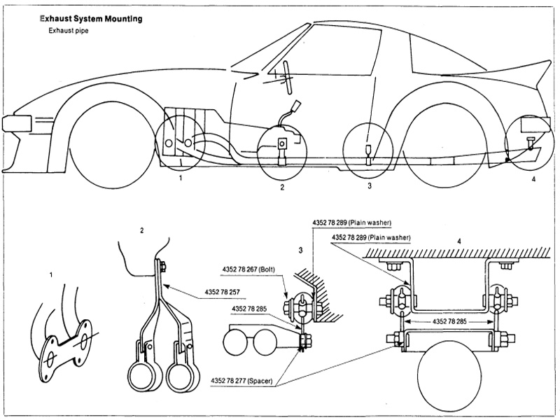
4. Exhaust header and pipe, header: 4352 78 250 pipe: 4352 78 260 Some of the main features of this exhaust system are:
- Both the header and pipe are fabricated from stainless steel.
- The header is a tubular design, and the pipe terminates in a megaphone.
- The header and pipe are joined by a sliding connection to allow for engine vibration and movement.
D. Lubrication group.
- Oil pump, 1058 78 220A The shaft and rotors in the competition oil pump are more resistant to wear and seizing.
- Oil pressure regulator assembly, 4352 14 250 This regulator will maintain oil pressure at 6.5 ± 0.5 kg/cm2.
- Engine oil cooler, 1058 78 180 This larger-than-stock cooler will increase cooling capacity by 50 percent over stock.
E. Cooling group.
- Water pump, 4801 15 010 The competition water pump is aluminum alloy.
- Water pump pulley, 4801 15 151 To reduce weight this pulley is made from aluminum alloy, and its larger-than-stock 130 mm diameter will enhance V-beit life and reduce the speed of the water pump.
- Radiator, 1058 78 190 The aluminum alloy competition radiator’s larger core will increase engine cooling capacity by 60 percent over stock.
- V-belt, 1058 78154 This notched V-belt is more resistant to heat, stretch and vibration.
F. Electrical system.
- Ignition coil, 4801 18 100 This higher output coil is exclusively designed for use with the Mazda competition capacitive discharge ignition (CDI).
- High tension wires, coil-to-distributor: 4352 18 110 distributor-to-spark plugs: 4801 18150 These high tension wires have a metal wire core to reduce voltage drop.
- Distributor, 4801 18 200 These are the main features of the distributor:
- It is breakerless, having a magnetic trigger.
- There is no advance mechanism.
- Ignitor and lead wiring, ignitor: 4801 18800 lead wiring: 4801 18 870 This fully transistorized ignition will provide a stable secondary voltage at high engine speeds. The lead wiring harness is specifically intended for this ignition.
- Alternator and alternator strap, alternator: 3997 18 300 strap: 4801 18 361 Alternator pulley part number: 0833-78-153A. The alternator output is 35 amps, and its pulley diameter is 75 mm.
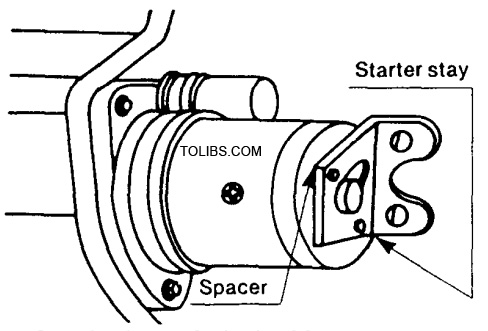
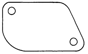
- Starter stay, 4352 18 401 spacer, 1281 17 383 The starter stay reduces vibration and prevents possible breakage of the transmission case. Note: When installing the stay, the spacer must be inserted between the stay and the starter motor.
- Spark plug, 4352 18 600 The heat range of this plug is 11.5, which is colder than stock.
- Fuel pump, 4352 18 250 This fuel pump has an output of 100 liters/hour. Two of them are needed to satisfy the racing engine’s minimum fuel flow requirement of 180 liters/hour.
Machining and Fabrication Operations and Procedures
A. Fabrication of oil separator tank.
- Use the stock oil filler pipe.
- The original filler pipe is too long and must have a 40 mm section removed from the middle. Cut it, reweld and drill holes as shown in the illustration.
- Fabricate the tank as shown, and weld it to the filler pipe.
- After Welding, check for any posible oil leaks.
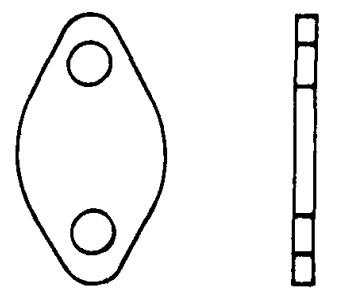
B. EGR port block-off plate.
- If your intermediate housing has an EGR port, it must be blocked off with a plate. We recommend aluminum approximately 3.0 mm thick.
- When installing the block-off plate, use a gasket or some silicone sealant.
C. Metering pump hole cover.
- If the metering pump shaft is not used as a mechanical tachometer drive, the hole must be covered with a plate. Make the plate of aluminum approximately 3.0 mm thick.
- A gasket must be used with the hole cover plate.
D. Weber carburetor float bowl extension.
For courses with very tight or long corners, this float bowl extension will help prevent fuel starvation. The float bowl extension fabrication procedure is as follows:
- Cut an appropriate hole on the side of the float chamber.
- Fabricate the bowl extension from sheet aluminum as shown in the illustration.
- Weld the bowl extension to the float chamber at four points only; if you weld all around the carburetor may distort.
- After welding, seal the bowl extension to the float chamber with Three Loy. The Three Loy may be held in place with clay or something similar until it hardens.
E. Exhaust System Mounting
F. Cold air induction box.
This is one of the best ways we have found to utilize the high pressure area at the front of the car for intake air, but its size, location and design are important to maximum performance. the important points of its design are outlined below.
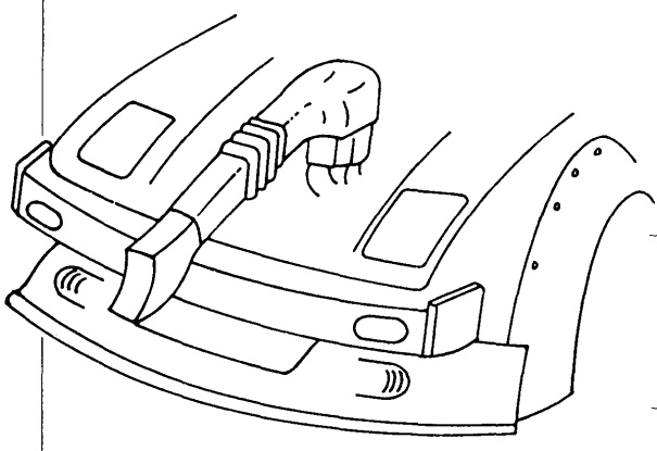
- The air intake section should be located in the right hand side of the radiator opening.
- We recommend fabricating the air intake and carburetor cold air box from fiberglass.
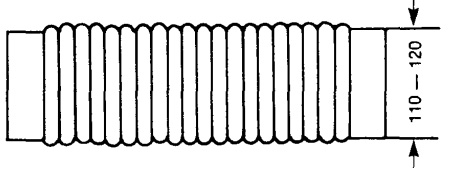
- The design of the carburetor cold air box is shown below:
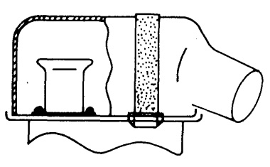
- The connecting duct can be any type of flexible hose with a minimum diameter of 110-120 mm
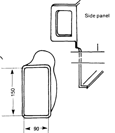
- Fabricate the intake section to he dimensions shown, and atach to right side panel as shown in the illustration:
- An air filter element is absolutely necessary. If dirt gets into the engine through the intake, compression is lost from wear on the internal gas seals. For a filter element material, Filtron has worked very well. Locate the element at the entrance to the carburetor cold air box. The intake system should be sealed very tight to completely prohibit any dirt or dust from entering the engine, so check for air leaks, holes or other openings.
G. Competition radiator installation.
- Fabricate the left and right side panels as shown in the illustrations below. All dimensions are given in millimeters. The hole in the right side panel is for the intake system.
- Install the side panels in the same location and manner as the stock versions.
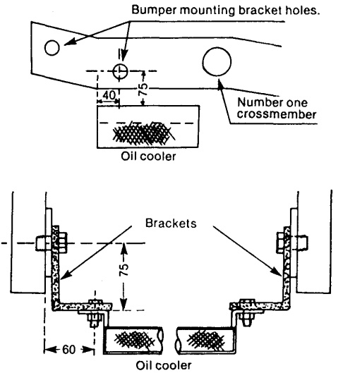
H. Competition oil cooler installation.
There are two possible locations for the oil cooler as shown in the illustrations below. In both cases, the competition oil cooler hoses can be used, in either the vertical-type or horizontal-type mounting.
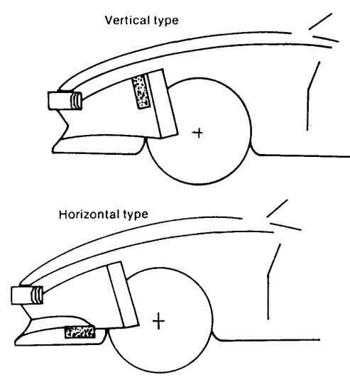
- The first location is referred to as the vertical-type, with the oil cooler mounted in front of the radiator and attached to the radiator support brackets with rubber mounts.
- The second location is referred to as the horizontal-type and is superior to the vertical-type, as it effectively lowers the oil temperature by approximately 18° F (10° C).
- The installation of the oil cool er in the horizontal location requires fabrication of mounting brackets as shown in the illustration.
- Install the brackets by utilizing the bumper bracket bolts, as shown in the illustration.