Mazda CX-5 Denso Sky Active Service Manual
MAZDA SKYACTIV-D Engine (EURO 6) Common Rail System (CRS) Service Manual
The name SKYACTIV was chosen for several innovativenext generation MAZDA technologies to evoke animage of vehicles that are not only "fun to drive", but achieve "superior environmental friendliness and safe-ty." This manual introduces the following six key SKYACTIV technologies.
SKYACTIV-D Features
- SKYACTIV-D takes the following measures to lower fuel consumption.
- Use of a variable valve lift mechanism to improve ignition stability when the engine is cold.
- Use of two-stage supercharging control to generate high levels of supercharging efficiently. As such low emissions performance, low fuel consumption performance, high torque, and high response are attained.
- Use of Exhaust Gas Recirculation (EGR) toclean exhaust gas and improve fuel economy.
- Use of i-stop to improve fuel economy, as well asto lower the amount of exhaust gas and idling noise.
- Low Compression Ratio
- Combustion performance is improvedvia a low compression ratio (14:0).
- Weight Reductions
- Aluminum alloy cylinder block
- Integrated exhaust manifold and cylinder head
- Weight Reductions and Reduced Mechanical Resistance Losses
- Optimized piston shape
- Lightweight crankshaft journals
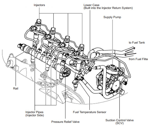
Mounting Figure for Primary CRS Parts
The primary parts for the SKYACTIV-D CRS are mounted as shown in the figure below.
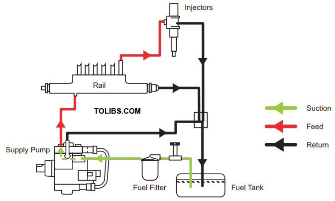
Fuel Flow
Fuel flows through the CRS as shown below.
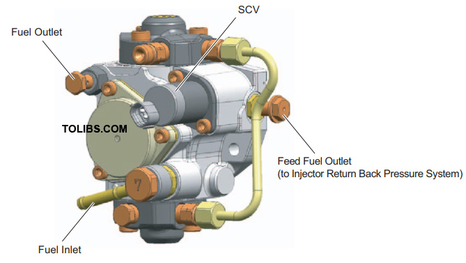
Outline Supply Pump
The supply pump used with the SKYACTIV-D engine CRS (HP3) complies with pressures up to 200 MPa. In addition, a port has been established to feed fuel to the injector return system used with the CRS. The fuel temperature sensor is separate from the pump, and is now set in the path between the supply pump and the fuel return.
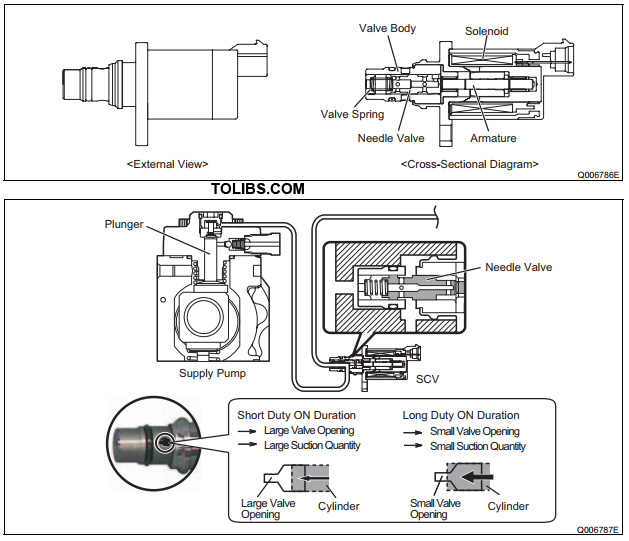
Suction Control Valve (SCV)
- The SCV used with the SKYACTIV-D engine CRS is a normally open SV3 type. The SV3 type has the following features.
- A more compact design compared to the SV1 type due to a smaller solenoid
- Improved valve sliding performance
Rail
The rail used with the SKYACTIV-D engine CRS is compliant with pressures up to 200 MPa. The rail uses a new model pressure relief valve.
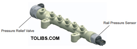
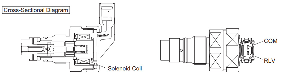
Pressure Relief Valve
The pressure relief valve controls rail fuel pressure. If rail pressure reaches or exceeds a specified value, a solenoid coil is energized to open a path in the valve and return fuel to the fuel tank, thereby reducing pressure to the specified value.
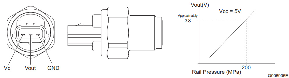
Rail Pressure Sensor
The rail pressure sensor is compliant with pressures up to 200 MPa.
Injectors
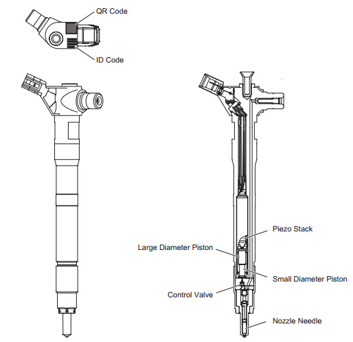
- The G3P type piezo injectors equipped with the SKYACTIV-D engine CRS can inject fuel at extremely high pressure (200 MPa). As a result, the atomization of the fuel mist from the nozzle is improved, leading to increased combustion efficiency, and reduced exhaust gas quantity.
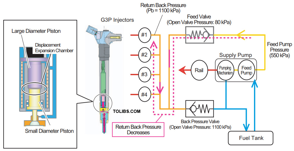
- A piezo injector primarily consists of a piezo stack, large diameter piston, small diameter piston, control valve, and nozzle needle.
- The piezo stack is a laminated body consisting of alternating layers of a substance called PZT (PbZrTiO3), and thin electrodes. By applying voltage, the characteristics of a piezo element are used to expand and shrink the stack via the inverse piezoelectric effect.
- Small displacements of the piezo stack are expanded by transmitting actuation from the large diameter piston to the small diameter piston.
- The small diameter piston moves the control valve to regulate the pressure inside the injector.
- The nozzle needle is moved up and down via control valve pressure control.
Operation
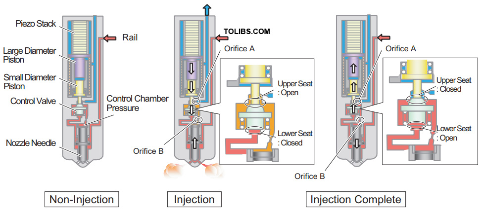
Non-Injection
When voltage is not applied to the piezo stack, the pressure in the control chamber and at the bottom of the nozzle needle is at the same value as fuel in the rail. The nozzle needle remains closed due to the difference in surface area exposed to pressure between the control chamber and bottom of the nozzle needle. Therefore, injection is not performed.
Injection
When voltage is applied to the piezo stack, the stack expands. The transmission of actuation power from the large diameter piston to the small diameter piston expands the displacement of the piezo stack and pushes the control valve down, thereby opening the upper seat and closing the lower seat. As a result, fuel is discharged from the control chamber to the leak path via orifice A, and control chamber pressure decreases. Since pressure on the bottom of the nozzle needle becomes greater than that of the control chamber, the nozzle needle is pushed up and injection begins.
Injection Complete
When the voltage applied to the piezo stack is removed, the stack shrinks, and both the large and small diameter pistons, as well as the control valve rise. Additionally, the lower seat opens and the upper seat closes. As a result, a fuel path to the control chamber opens, and fuel pressure in the control chamber quickly returns to the same pressure as the rail. Therefore, the nozzle needle is pushed downward, and fuel injection stops.
Injector Return Back Pressure System
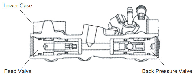
When the injector return side is dry (no fuel) and air enters the displacement expansion chamber inside the injector, the ability to transmit piezo stack displacement is lost, and injection is no longer possible. To prevent the aforementioned circumstances, fuel is sent to the injector return side from the supply pump via the feed valve to apply back pressure. The air is therefore compressed and eliminated to improve startability. The injector return system is built into the lower case of the engine compartment. Injector return system construction and operation are detailed below.
Construction
Injector return system construction is shown in the figure below.
REFERENCE
In addition to the learning performed automatically at three different pressure levels, the learning performed by a dealer (with diagnostic tools) when an injector or the engine ECU is replaced adds learning at 140 MPa and 197 MPa for a total of five different levels. However, learning at 140 MPa and 197 MPa is performed while the engine is in an idle-up state with an eye towards supply pump reliability