Mazda RX-4-929 WORKSHOP MANUAL (Chassis)

1976 MazdaRX-4-929 WORKSHOP MANUAL (CHASSIS)
This manual is a supplement to the RX-4, 929 (CHASSIS) workshop manual. Service information contained in this manual covers only those features that are new for 1975 RX-4, 929 (CHASSIS). Refer to the RX-4, 929 (CHASSIS) workshop manual for service procedures common to previous and 1975 models.
BRAKE
- Power Brake Unit The power piston diameter has been changed from 6" to 7.5". Since its construction and function are the same as before, service should be performed based on the Workshop Manual.
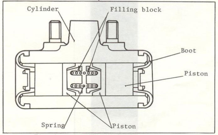
- Rear Wheel Cylinder The shapes of the rear wheel cylinder and material have been changed. Since disassembling, checking, assembling and service deta are the same as before, service should be performed based on the Workshop Manual.
| Models | Car Nos. | Production Dates |
| 929 Sedan | No. 155538 | Oct. 2, 1974 |
| 929 Wagon | No. 116233 | Sept. 28, 1974 |
| RX-4 Sedan RX-4 Wagon |
Will be applied from our November on 1974 production. |
MazdaRX-4-929 WORKSHOP MANUAL
Rear Axle
- Final Gear Ratio The final gear ratio has been changed from 3,900 to 3,909. This modification will be applied from our October production in 1975.
- Ring Gear Tightening Torque In order to further improve the mechanical characteristic of the ring gear bolts, the material of the bolts has been changed. According to this modification, the tightening torque of the ring gear bolts has been also changed from 5.5- 6.5 m-kg (40-47 ft-lb) to 6.5 -7.5 m-kg (47 -54 ft-lb). (Refer to Service Information M024/75).
| Models | Car Nos. | Production Dates |
| 929 Sedan | No. 164708 | December 13, 1974 |
| 929 Wagon | No. 119474 | December 13, 1974 |
| RX-4 (573 cc X 2 =35.0 cu-in X 2) | No. 155719 | December 24, 1974 |
Steering
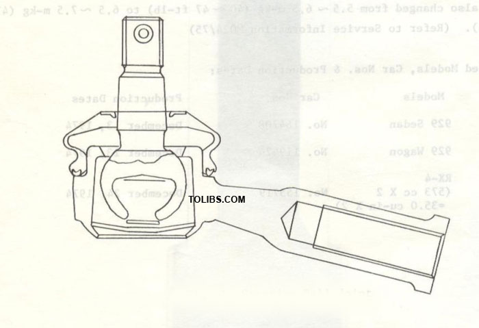
Steering Ball Joint
New ball joint manufactured by T.R.W Co., Ltd,, is put in use for all RX-4 and 929 models. The configuration of the knuckle arm, pitman arm and center link have been altered accordingly.
The tightening torque of the ball joint nuts has been changed to 3.0-4.5 m-kg (22-33 ft-lb) from 2.5-3.5 m-kg (18-25 ft-lb). (Refer to Service Information M038/75)
| Models | Car Nos. | Production Dates |
| 929 Sedan | No. 170900 | February 4, 1975 |
| 929 Hard Top | No. 170901 | February 4, 1975 |
| 929 Wagon | No. 121672 | February 4, 1975 |
| RX-4 Sedan | No. 155749 | February 5, 1975 |
| RX-4 Hard Top | No. 155750 | February 5, 1975 |
| RX-4 Wagon | From September production in 1975 |
Steering Ball Joint
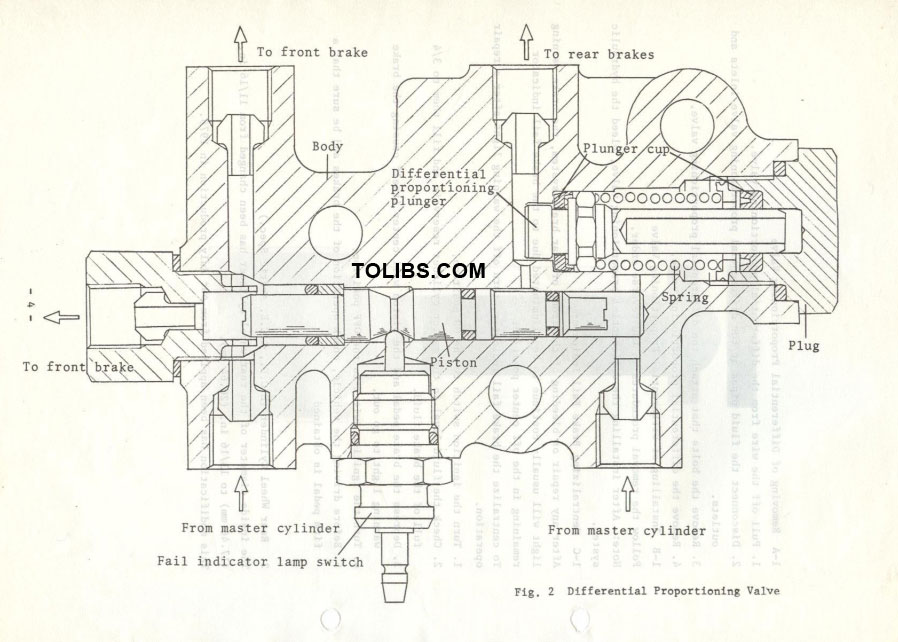
Differential Proportioning Valve (E.C.E., E.C.E. Arctic Spec.) The differential proportioning valve has been newly equipped on E.C.E. vehicles, and the fail indicator is included in this valve.
The differential proportioning valve is serviced as an assembly and never adjusted or overhauld. This modification has been applied from our July production in 1975.
Removing of Differential Proportioning Valve
- Pull off the wire from the differential proportioning valve.
- Disconnect the fluid pipes at the differential proportioning valve inlets and outlets.
- Remove the bolts that attach the differential proportioning valve.
- Remove the differential proportioning valve.
Installing of Differential Proportioning Valve
Follow the removal procedures in the reverse order.
Note: After installing the differential proportioning valve, bleed the hydraulic system.
Centralizing Brake Fail Indicator
After any repair or bleeding of the front or rear brake system, the brake warning light will usually continue to be illuminated due to the brake fail indicator remaining in the off center position. To centralize the brake fail indicator, turn off the warning light after a repair operation.
- Turn the ignition switch to the ON position.
- Check the fluid level in the master cylinder reservoir and fill them to 3/4 full of the brake fluid.
- Depress the brake pedal and the piston will center itself causing the brake warning light to go out.
- Turn the ignition switch to the OFF position.
- Before driving the vehicle, check operation of the brakes and be sure that a firm pedal is obtained
Rear Wheel Cylinder (E.C.E., E.C.E. Arctic Spec.)
The inside diameter of the rear wheel cylinder has been changed from 11/16 in. (17.46 mm) to 13/16 in, (20,64 mm). This modification has been applied from our July production in 1975.
Suspension
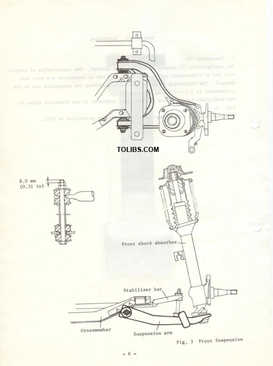
Suspension Arm
The configuration of suspension arm has been altered. The installation of suspension arm to crossmember and that of stabilizer bar to suspension arm have been changed. The tightening torque of the bolts attaching the suspension arm to the The crossmember stabilizer is bar 7.9-attaching 9.5 m-kgnut (54should — 69 fbe t-lb) tightened . to the dimension shown in Fig. 3
1975 MazdaRX-4-929 WORKSHOP MANUAL
DESCRIPTION
The clutch is of the single dry disc type. The clutch assembly consists of the clutch disc assembly, clutch cover and pressure plate assembly and clutch release mechanism. The clutch operating mechanism is of the hydraulic type, consisting of a dash mounted master cylinder and a clutch release cylinder mounted on the clutch housing.
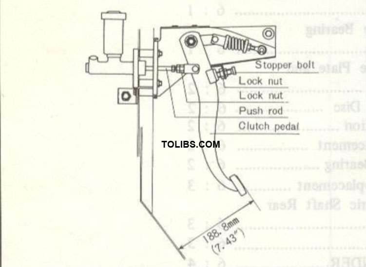
CLUTCH PEDAL ADJUSTMENT
The free travel of the clutch pedal before the push rod contacts with the piston should be 0.5 to 3.0 mm (0.02 to 0.12 in). To adjust the free travel, loosen the lock nut and turn the push rod until the proper adjustment is made. Tighten the lock nut after adjustment is completed.
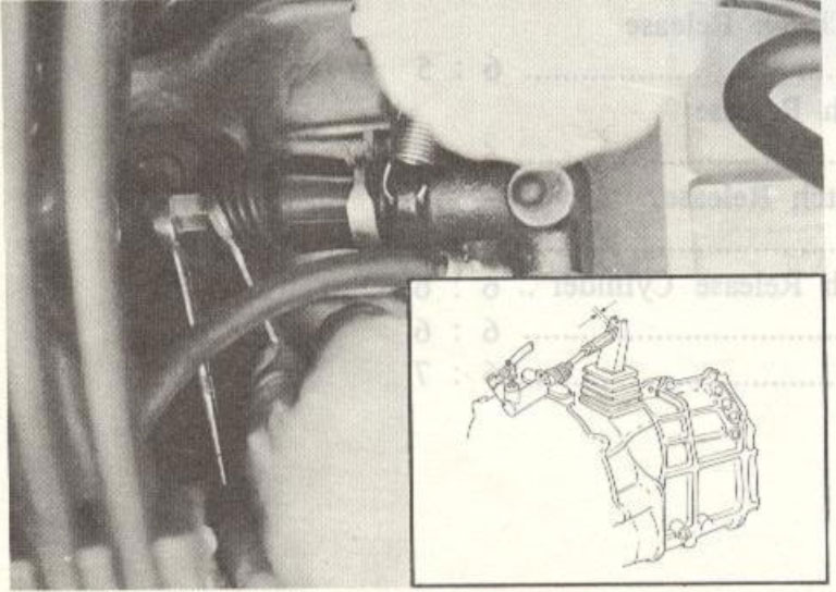
RELEASE FORK ADJUSTMENT
To adjust the free play, proceed as follows :
- Unhook the release fork return spring from the fork.
- Loosen the release rod lock nut and turn the free play adjusting nut until the correct free play is obtained. The free play is 3.0 ~ 4.0 mm (0.12 ~ 0.16 in).
- Tighten the lock nut and hook the return spring.
CLUTCH REMOVAL
To remove the clutch from the vehicle, proceed as follows:
- Remove the transmission.
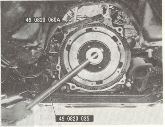
- Install the ring gear brake (49 0820 060A).
- Remove the 4 standard bolts and 2 reamer bolts holding the clutch cover assembly to the flywheel and remove the clutch cover assembly and the clutch disc.
- Straighten the tab of the lockwasher. With the wrench (49 0820 035), loosen the nut that attaches the flywheel to the eccentric shaft and remove the nut.
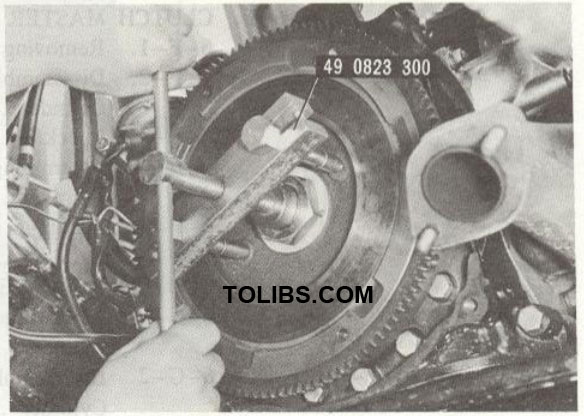
Lossening Flywhell Nut
Removing flywheel
Using the puller (49 0823 300), remove the fly wheel from the eccentric shaft.
Remove the return spring for the clutch release bearing and slide off the release bearing. Pull the release fork outward until the spring clip of the fork releases from the ball pivot. Remove the fork from the clutch housing.
CLUTCH INSPECTION
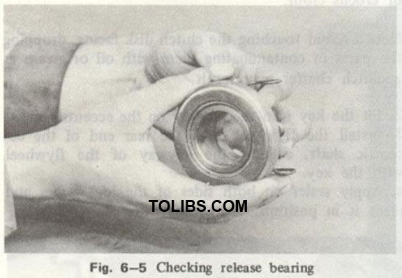
Checking Release Bearing and Fork
Note: The release bearing is packed with lubricant which is intended to last the whole life time of the bearing. Therefore, the bearing must not be washed in gasoline or any other solvent. Check the release bearing by pressing and turning the front race slowly by hand. Replace if the bearing feels rough or seems noisy when turning.
Examine the clutch housing carefully to be certain there are no burrs on the outer surface of the clutch housing which pilots the release bearing. Check the release fork for crack or bend. If necessary, replace the fork.
Checking Pressure Plate and Cover Assembly
Check the contact surfaces of the pressure plate with the clutch facing for wear, damage or warpage. If it is slight, correct it by lapping with compound or by turning a lathe. But if severe, replace with a new one. Check the diaphragm spring and cover and if any wear or damage is found, replace the pressure plate and cover assembly.
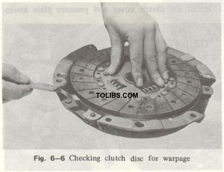
Checking Clutch Disc
Inspect the clutch disc for warpage with a dial indicator or a feeler gauge, as shown in Fig. 6-6. If it is more than 1.0 mm (0.039 in), replace with a new one.
Excessively worn facing will cause slippage or score the pressure plate and flywheel due to the projected heads of rivets. Check the depth between the facing surface and the rivet using a depth gauge, as shown in Fig. 6-7. If the reading is less than 0.30 mm (0.012 in), replace the clutch disc.

If oil is evident on the facing, clean or replace the facing and eliminate the cause of oil leakage. Make certain that the clutch disc slides easily on the main drive shaft without any excessive play.
Flywheel Inspection
Inspect the contact surface of the flywheel with the clutch facing for burnt surface, scored surface or rivet grooves. If it is slight, it can be reconditioned by grinding in a lathe. If the damage is deep, the flywheel should be replaced. Check the ring gear teeth and replace if the ring gear teeth are broken, cracked or seriously burred. Check the oil seal contacting surface of the flywheel for roughness. Repair or replace the flywheel if necessary.
Note: On the vehicle equipped with an automatic transmission, the ring gear and drive plate should be replaced as an assembly.