Carburetor Training Manual for Mazda Car
Mazda Carburetor Training Manual
This training manual has been prepared for training service personnel of authorized Mazda dealers. The models covered are 1979 and 1980 Mazda 121, 121L, 929L, 626, 323, GLC, RX-7, B2000, B1800, B1600, E2000, E1600, E1300. All information, photographs and drawings contained in this manual were the best available at printing time. Toyo Kogyo reserves the right to make changes in designs without previous notice.
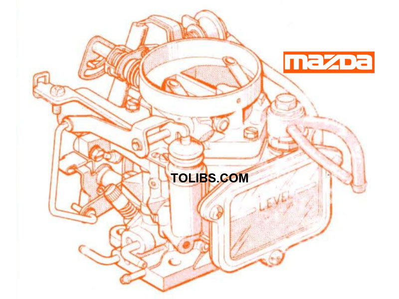
CARBURETOR TYPE
Down-draft
Two-stage
Two-barrel
Applied models: 121, 121L, 929L, 626, 323, GLC. E1300, B2000, B1800, B1600.
SYSTEM OPERATION
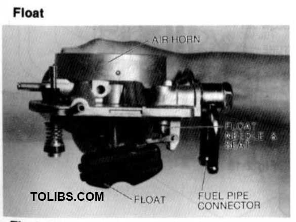
FLOAT SYSTEM
Fuel enters the carburetor at the fuel inlet and flows through the float needle valve into the chamber. When the fuel reaches the proper level, the rising float closes the needle valve. The needle valve is spring-loaded to provide uniform seating under all operating conditions. The float chamber is internally vented into the air horn.
SLOW FUEL SYSTEM
IDLE OPERATION
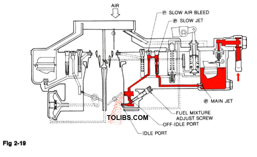
During the idle and early part-throttle operation, air flow through the venturi is very low and is not great enough to cause fuel to flow from the main nozzle. Fuel from the float chamber flows through the main jet and slow jet, and mixes with air entering through the slow air bleed. The air-fuel mixture then flows down through the slow fuel passage and into the idle port.
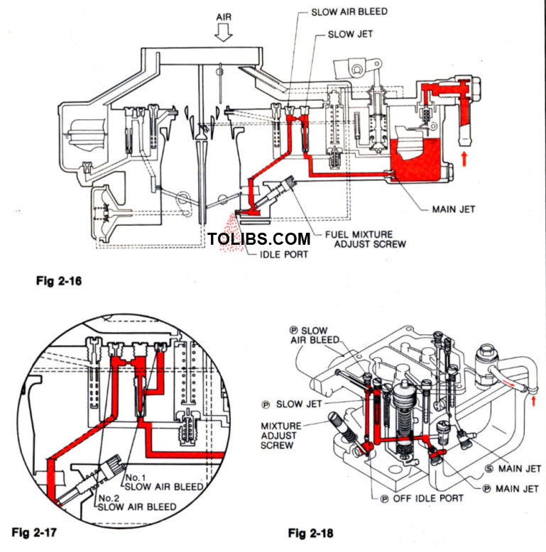
Some models use No.1 and No.2 slow air bleeds to supply additional air for engine requirements
OFF-IDLE OPERATION
The idle adjust screw controls the amount of fuel mixture which enters the intake manifold. As the primary throttle valve opens, air-fuel mixture drawn from the off-idle port (slow port) provides smooth transition from idle to the high-speed system.
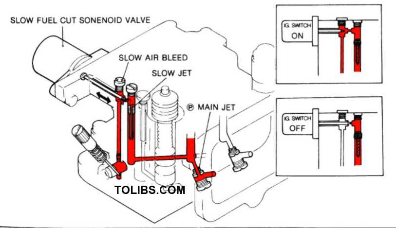
SLOW FUEL CUTOFF
To prevent run-on, a solenoid-actuated fuel cutoff valve is situated in the slow fuel passage. When the ignition switch is turned off, power leaves the solenoid, closing the valve.
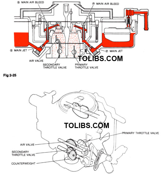
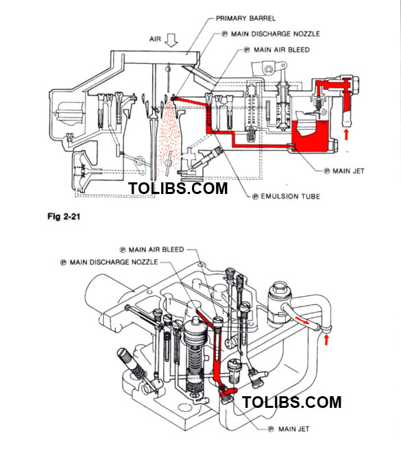
PRIMARY MAIN FUEL SYSTEM
PART-THROTTLE AND FULL THROTTLE OPERATION
During part-throttle and full throttle operation, the difference in pressure between normal air pressure in the float bowl and the vacuum in the venturi forces fuel to flow through the main metering system. Fuel from float bowl flows through the main jet, mixes in the emulsion tube with air entering through the main air bleed and sprays through the main nozzle into the venturi.
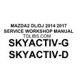
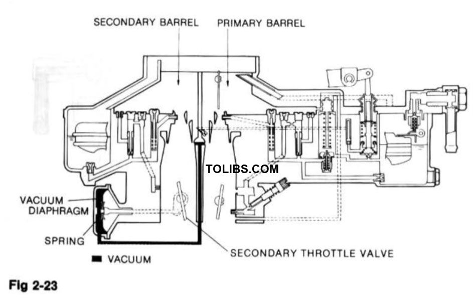
SECONDARY OPENING SYSTEM
VACUUM CONTROL
After the lockout lever is released, the secondary throttle valve is pulled open (through a diaphragm) by vacuum formed in the venturi. The valve is held open against the spring tension by vacuum from the vacuum pick-up bottle.
MECHANICAL CONTROL
The secondary throttle valve is mechanically connected to the primary throttle lever. When the secondary throttle valve begins to open, manifold vacuum appears below the air valve. The air valve reacts to the pressure drop and starts O open against the counterweight.