Haynes Weber 28/36 DCD Book manual
Type 28/36 PCD carburettor
1 Introduction
The Weber 28/36 carburettor is of the downdraught type and has two barrels to supply the primary and secondary functions: the primary barrel is of 28.0 mm diameter at the throttle valve location and the secondary barrel is of 3.60 mm diameter. Each throttle valve is mounted on separate shafts and the valves are of the differential or progressive choke type. The linkage between the two throttle valves is arranged so that the secondary throttle valve does not commence to open until the primary throttle valve is j open.
The carburettor is normally fitted to the engine as a single unit with both barrels feeding a common inlet manifold, the most common arrangements being as follows:
- One unit on a four-cylinder in-line engine
- One unit on a six-cylinder in-line engine
The carburettor identification mark is located on the lower flange outer surface.
2. Construction
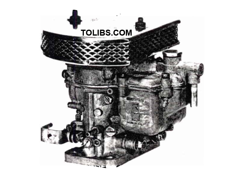
The main body and cover of the Weber 28/36 DCD carburettor are made of die-cast aluminium or zinc alloy (Mazak), the mounting flange being machined flat for fitting on the inlet manifold. The upper face of the cover is also machined flat and incorporates four threaded holes for the fitting of an air cleaner (photo).
The throttle valves and shafts are of brass and the shafts run directly in the carburettor body. All fuel and air jets and emulsion tubes are of brass construction and are screw fittings into the main body. Internal channels of the main body and cover are mostly drilled and are sealed with lead plugs where necessary. The fuel float assembly comprises two semi-floats which are each of two halves soldered together; they are made of thin brass sheet.
3. Operation
Cold starting
The tarting device fitted to type DCD carburettors operates independently of the main circuit and may be considered as a separate carburettor within the main carburettor. When the choke cable is pulled, the starting device operat¬ ing lever turns the control shaft which lifts the starting valve off of its seat. Reference to Fig. 6.3 will show that fuel from the float chamber (7) is driven through the channel (53) to arrive at the starter fuel jet (52). Air entering through the air correction jet (51) and the bypass channel emulsifies the fuel as it i drawn through the starting jet emulsion holes and the bypass channel. The mixture is then drawn through the channel (48) and past the starter valve (50) where additional air from the channel (49) weakens the mixture. The final mixture is drawn through the channel (54) and into both the primary and secondary carburettor barrels at the engine side of the throttle valves.
Once the engine starts, the vacuum in the channels (54) and (57) increases to such an extent that the starter plunger (56) is pulled against spring pressure from the seat (55). Additional air is thus admitted to the mixture to allow the engine to continue running. The starting device has a progressive action made possible by the tapered shape of the valve head. Lowering the valve will reduce the amount of mixture admitted to the engine. The supply will cease when the valve is completely shut.
Idling and progression
Refer to Fig. 6.4 and note that when the engine is idling the secondary throttle valve (37) is completely shut, but the primary throttle (13) is slightly open, according to the throttle idling adjustment screw setting. Fuel is drawn from the float chamber hrough an internal channel to the fuel jet in the idling jet (34). On passing through the fuel jet, air is introduced to the fuel from the calibrated bush (35) and the holes in the idling jet tube. The fuel then becomes emulsified.
The mixture then passes through the channel (32), past the idling mixture adjustment screw (20), through the idling feed hole (31) and into the primary carburettor throat at the engine side of the throttle valve. The idling adjustment screw (20) has a tapered end and can therefore be adjusted to admit more or less fuel/air mixture as necessary.
When the primary throttle valve (13) is opened slightly to increase the engine speed, the progression hole (36) is brought into action to provide additional fuel. This is necessary to prevent a flat spot occurring before the main primary fuel supply system comes into operation.
When the primary throttle valve (13) is approximately -J open, the secondary throttle valve (37) will commence to open. This action causes the secondary progression hole (38) to be brought under engine vacuum. Fuel is then drawn from the float chamber to the secondary idling jet(27), where air is introduced from the calibrated bush (26). The mixture passes through the channel (29) and thus emerges from the progression hole (38). With either throttle valve fully open, the progression system for the particular carburettor barrel ceases.
Normal running
Under full throttle and high speed cruising conditions, the throttle prates wJI be sufficiently tar from the idling and progress^ holes to prevent them from admitting fuel and the main fuel supply circuits will be brought into action. Refer to Fig. 6.5 and note that fuel from the float chamber (7) passes through the main jets (8) and channels (9) to the emulsion tube wells (11). At the same time, air is drawn through the air corrector jets (1), through the centre of the emulsion tubes (12) and via the emulsion tube holes to the fuel. The fuel then becomes emulsified and is drawn through the nozzles (17) and auxiliary venturis (16) and thus mixes with the main air supply as it is drawn through the chokes (15) and into the engine.
Under static conditions the level of fuel in the float chamber and emulsion tube will be identical; however, as the engine speed increases and the fuel flow is faster, the fuel level in the emulsion tube drops. By providing additional holes in the lower part of the emulsion tube, the necessary air correction is made possible at the higher engine speeds. The main fuel supply circuits of the primary and secondary carburettor barrels operate progressively and there is a certain amount of overlapping as each circuit is brought into action.
Acceleration
To provide the engine with a rich mixture when accelerating, the carburettor is equipped with an acceleration pump which is operated by the primary throttle of the carburettor and injects only into the primary venturi. Reference to Fig. 6.6 will show that when the primary throttle valve is closed, the lever (45) lifts the operating rod (44) under the action of the coil spring. The piston (42) is pulled up the piston bore against the pressure of the spring (41) and fuel is drawn from the float chamber (7) through the intake valve (47).
When the primary throttle valve is opened, the lever (45) moves away from the operating rod (44) and allows the piston (42) to move down the bore under the action of the spring (41). The ball in the intake valve (47) prevents fuel returning to the float chamber (7) and the fuel is forced along the internal channel (43), past the delivery valve (4), through the pump jet (39) and into the primary venturi. The inlet valve (47) may or may not incorporate a discharge orifice according to the application, but where there is one, a certain amount of fuel is discharged back into the float chamber during the ecceleration pump piston stroke. By fine calibration of the discharge orifice, it is possible to determine the exact quantity of fuel injected by the acceleration pump.
4. Removal and refitting
Note: The following procedure gives a general rather than a specific method of removing and refitting the carburettor, as much will depend on the location within the vehicle.
- Unscrew and remove the retaining nuts and withdraw the air cleaner cover and filter gauze. Unscrew the air cleaner retaining screws, being very careful not to drop them into the carburettor barrels.
- Loosen the fuel supply hose clip and pull the hose from the inlet pipe.
- Slacken the choke cable retaining screws on the starting device and pull the cable clear.
- Disconnect the throttle control rod from the throttle lever.
- Pull the ignition advance tube from the vacuum pipe on the side of the carburettor.
- Where fitted, disconnect the automatic transmission controls from the carburettor
- Unscrew and remove the carburettor mounting nuts then withdraw the unit over the mounting studs.
- Remove the inlet manifold gasket and clean all traces from the contact faces of the inlet manifold and carburettor.
5. Disassembly
- Thoroughly clean the carburettor exterior and wipe dry.
- Referring to Fig. 6.7, unscrew the filter inspection plug (11). remove the gasket (10) and extract the fuel filter (8) (photos).
- Using a suitable screwdriver, unscrew the carburettor cover retaining screws (3) together with the spring washers, then carefully withdraw the cover (1) from the carburettor body (77). With a new carburettor this is straightforward, but where the seat of the starter plunger spring (7) is a loose fit in the cover
- it may easily fall out together with the spring (7) and plunger (6) (photo).
- Remove the gasket (12) from the carburettor cover (1).
- Invert the carburettor cover (1) so that the float assembly is uppermost, then use a suitable diameter pin punch to release the float fulcrum pin (15) from the two posts.
- Using a pair of flat pliers, extract the fulcrum pin (15), then carefully withdraw the float (16), at the same time disconnecting the long tab on the float arm from the spring hook on the end of the needle valve needle (photo).
- Lift the needle from the needle valve (14) seating (photo).
- Using a 10 mm socket, unscrew the needle valve seating and remove the gasket (13).
- If the starter plunger spring seat is still retained in the cover
- use a plastic rod entered through the lockwasher (4) and tap out the seating, spring (7), and plunger (6). 10 The lockwasher (4) is retained in the carburettor cover (1) by local peening and unless the starter plunger seat (5) requires renewal (see overhaul Section 6) neither item should be removed. If removal is necessary, extract the lockwasher (4) and use a small file to remove the peening; the plunger seat (5) can then be driven out from below by using a suitable diameter drift. 11 Unscrew and remove the main jet holders (39) together with the gaskets (37) and place them in separate containers