Mazda CX-9 Wiring Diagram
2007 Mazda CX-9 Wiring Diagram
FOREWORD
This wiring diagram incorporates the wiring schematics of the Mazda CX-9 and available optional equipment.Actual vehicle wiring may vary slightly depending on optional equipment or local specifications, or both. For proper repair and maintenance, a thorough familiarization with this manual is important, and itshould always be kept in a handy place for quick and easy reference.
WARNING
Servicing a vehicle can be dangerous. If you have not received service-related training, the risks of injury, property damage, and failure of servicing increase. The recommended servicing procedures for the vehicle in this workshop manual were developed with Mazda-trained technicians in mind. This manual may be useful to non-Mazda trained technicians, but a technician with our service-related training and experience will be at less risk when performing service operations. However, all users of this manual are expected to at least know general safety procedures.
This manual contains "Warnings" and "Cautions" applicable to risks not normally encountered in a general technician's experience. They should be followed to reduce the risk of injury and the risk that improper service or repair may damage the vehicle or render it unsafe. It is also important to understand that the "Warnings" and "Cautions" are not exhaustive. It is impossible to warn of all the hazardous consequences that might result from failure to follow the procedures.
The procedures recommended and described in this manual are effective methods of performing service and repair. Some require tools specifically designed for a specific purpose. Persons using procedures and tools which are not recommended by Mazda Motor Corporation must satisfy themselves thoroughly that neither personal safety nor safety of the vehicle will be jeopardized.
The contents of this manual, including drawings and specifications, are the latest available at the time of printing, and Mazda Motor Corporation reserves the right to change the vehicle designs and alter the contents of this manual without notice and without incurring obligation.
Parts should be replaced with genuine Mazda replacement parts or with parts which match the quality of genuine Mazda replacement parts. Persons using replacement parts of lesser quality than that of genuine Mazda replacement parts must satisfy themselves thoroughly that neither personal safety nor safety of the vehicle will be jeopardized.
Mazda Motor Corporation is not responsible for any problems which may arise from the use of this manual. The cause of such problems includes but is not limited to insufficient service-related training, use of impropertools, use of replacement parts of lesser quality than that of genuine Mazda replacement parts, or not being aware of any revision of this manual.
Content Information:
- GENERAL INFORMATION
- ENGINE
- SUSPENSION
- DRIVELINE/AXLE
- BRAKES
- TRANSMISSION/TRANSAXLE
- STEERING
- HEATER, VENTILATION &AIR CONDITIONING (HVAC)
- RESTRAINTS
- BODY & ACCESSORIES
- ALPHABETICAL INDEX
Electrical System General Procedures
ELECTRICAL PARTS
- Battery Cable
- Before disconnecting connectors or removing electrical parts, disconnect the negative battery cable.
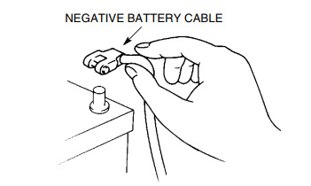
- Before disconnecting connectors or removing electrical parts, disconnect the negative battery cable.
- Wiring Harness
- To remove the wiring harness from the clip in the engine room, pry up the hook of the clip using a flathead screwdriver.
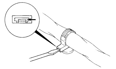
- Caution: Do not remove the Harness protective tape. Otherwise, the wires could rub against the body, which could result in water penetration and electrical shorting.
- To remove the wiring harness from the clip in the engine room, pry up the hook of the clip using a flathead screwdriver.
CONNECTORS
- Data Link Connector
- Insert the probe into the terminal when connecting a jumper wire to the data link connector.
- Caution: Inserting a jumper wire probe into the data link connector terminal may damage the terminal.
- Insert the probe into the terminal when connecting a jumper wire to the data link connector.
- Disconnecting Connectors
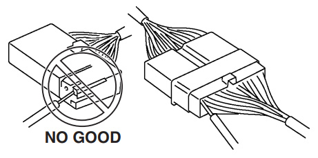
- When disconnecting connector, grasp the connectors, not the wires.
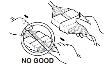
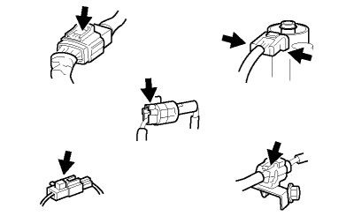
- Connectors can be disconnected by pressing or pulling the lock lever as shown.
- When disconnecting connector, grasp the connectors, not the wires.
- Locking Connector
- When locking connectors, listen for a click indicating they are securely locked.
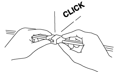
- When locking connectors, listen for a click indicating they are securely locked.
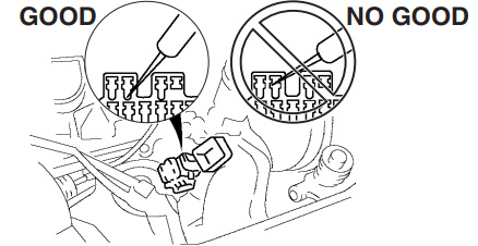
- Inspection
- When a tester is used to inspect for continuity or measuring voltage, insert the tester probe from the wiring harness side.
- Inspect the terminals of waterproof connectors from the connector side since they cannot be accessed from the wiring harness side.
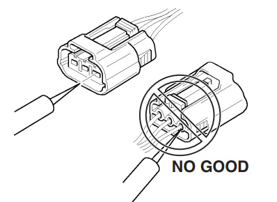
- Caution: To prevent damage to the terminal, wrap a thin wire around the tester probe before inserting into terminal.
- When a tester is used to inspect for continuity or measuring voltage, insert the tester probe from the wiring harness side.
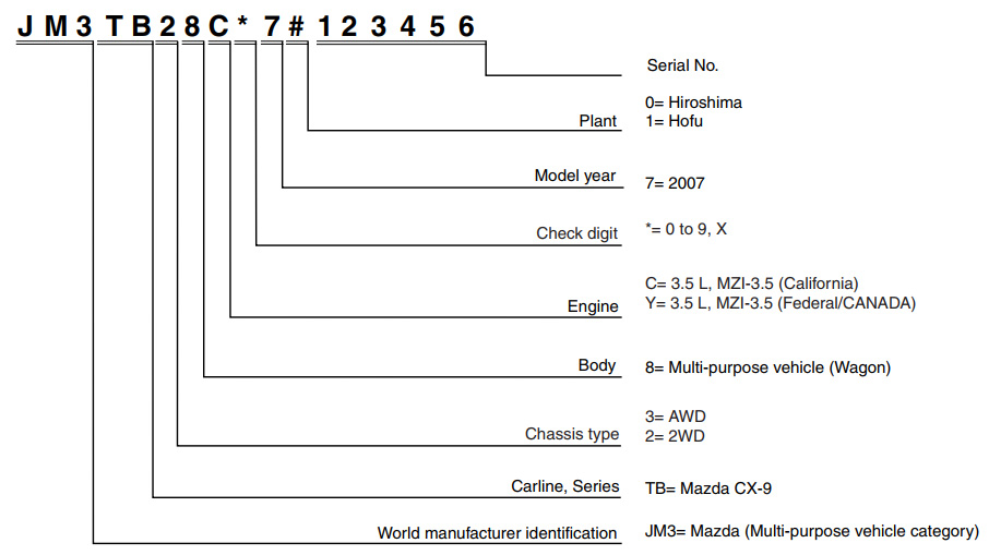
VEHICLE IDENTIFICATION NUMBER (VIN) CODE
- JM3 TB28C*7# 100001-
- JM3 TB28Y*7# 100001-
- JM3 TB38C*7# 100001-
- JM3 TB38Y*7# 100001-
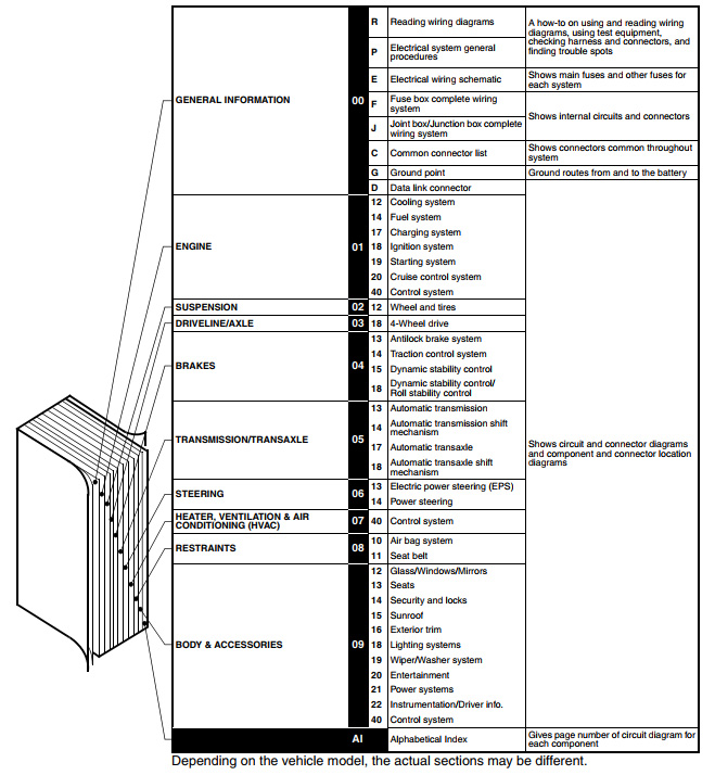
Reading Wiring Diagrams
CONTENTS OF WIRING DIAGRAMS
- This manual comprises the sections shown below.
GROUND POINTS
- This shows ground points of the harness.
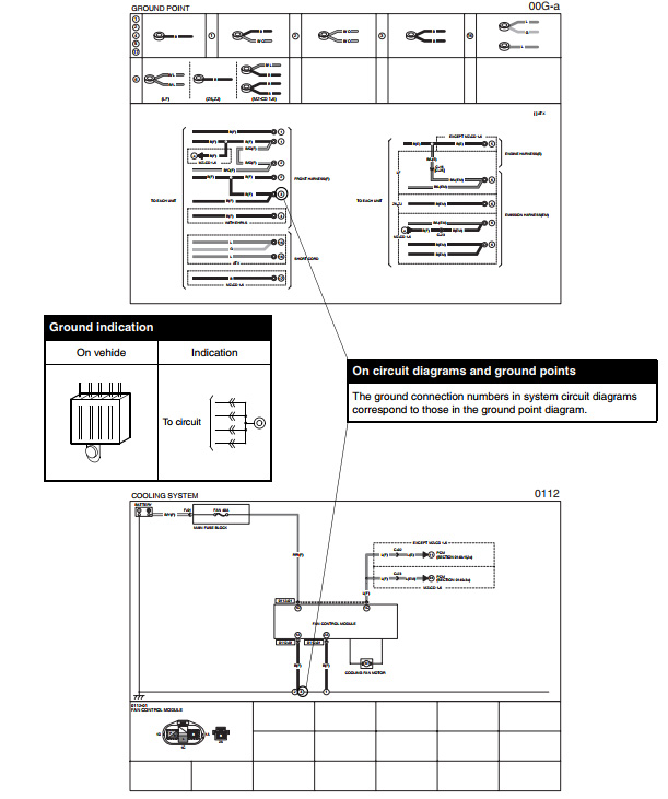
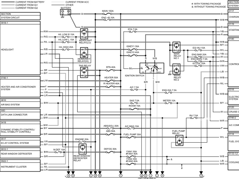
SYSTEM CIRCUIT DIAGRAM/CONNECTOR DIAGRAM
- These diagrams show the circuits for each system, from the power supply to the ground. The power supply side is on the upper part of the page, the ground side on the lower part. The diagrams describe circuits with the ignition switch off.
Below is an explanation of the various points in the diagram.
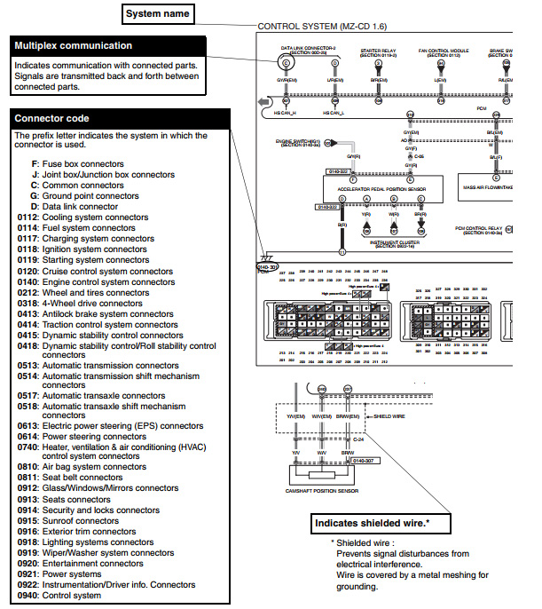
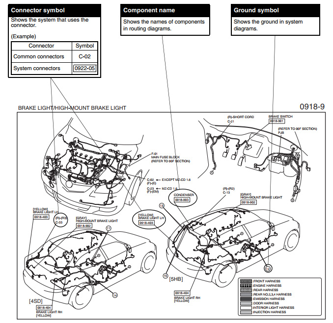
ROUTING DIAGRAM
- The routing diagram shows where electrical components are on the system circuit diagram by call out line and connector symbols.
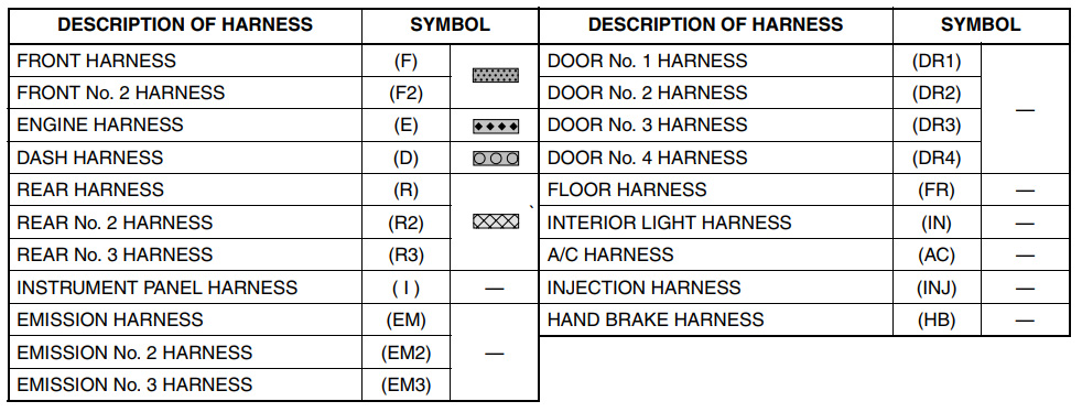
HARNESS SYMBOLS
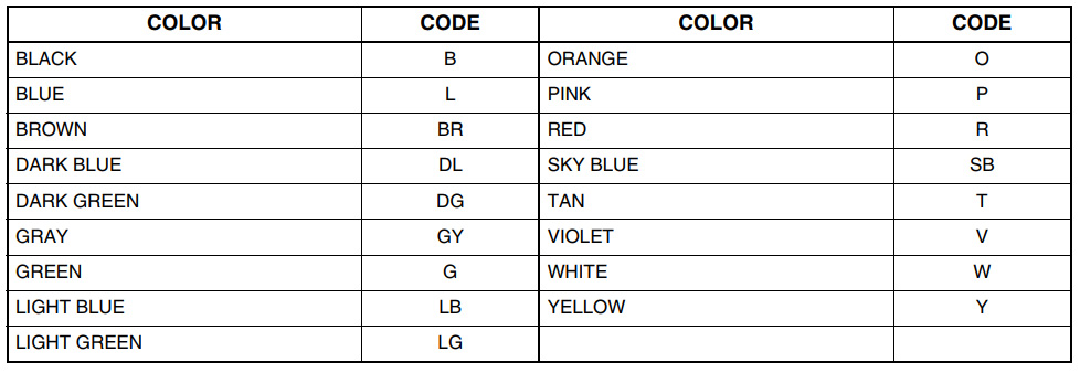
WIRING COLOR CODE
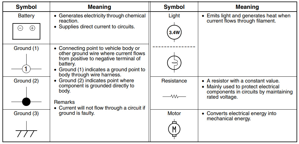
SYMBOLS
SERVICE WARNING AND CAUTION FOR VEHICLES WITH SRS AIR BAG SYSTEM
If the SRS air bag system inspection is not performed correctly in accordance with the workshop manual procedures it could cause the system to operate (deploy) accidentally, resulting in injury. Always follow the service warnings and cautions in the workshop manual when performing the SRS air bag system-related inspection or servicing.
SERVICE WARNING FOR VEHICLES WITH DISCHARGE HEADLIGHTS
If the discharge headlight inspection and servicing is not done using the correct procedures in the workshop manual, it could result in electrical shock. Always follow the service warnings and cautions in the workshop manual when performing the discharge headlight-related inspection or servicing.