Mazda Capella 1800 Workshop Repair Manual

THIS MANUAL COVERS: ALL MAZDA 929 MODELS
This Repair Guide covers the range of Mazda 929 Capella 1800 models, being the piston engine version of the Mazda RX-4 Rotary Engine Vehicle. The engine of the Mazda 929 is a 1,769 c.c. (108 cu.in.) unit, with four cylinders and an overhead camshaft. The camshaft runs in bearings (shells) in the cylinder head. The crankshaft is supported in five bearings of the shell-type and drives the camshaft and the oil pump by means of chains. All models are fitted with a four- or five speed manual transmission or a Borg-Warner automatic transmission.
General Servicing Notes
The servicing and repair instructions in this Repair Guide are laid out in an easy-to-follow step-by-step order and no difficulties should be encountered if the text and diagrams are followed carefully and methodically. The author of this Repair Guide has attended a comprehensive Mazda Service Training Course and all operations have as far as possible been carried out without the use of special tools. Even if the number of a special service tool is given, we have tried to overcome this by giving alternative methods.
INSPECTION OF PARTS
Shows an exploded view of the final drive and differential assembly and should be referred to when identifying the following parts:
Crown Wheel and Pinion:
Check the crown wheel and the pinion for damage or excessively worn teeth, damaged bearing journals and splines. Inspect the crown wheel for chipped teeth. If necessary, crown wheel and pinion must be replaced together as a set.
Differential Gears:
Inspect the differential side gears and pinions and the thrust washers for wear, cracks, chipped teeth or any other damage. Check the fit of the differential pinion shaft in the bevel pinions and fit new parts if the clearance is excessive. Slide the two side gears over their respective axle shafts to check their side play on the splines. Side gears or axle shafts must be replaced if the play exceeds 0.3 mm (0.012 in.).
Bearings:
Bearings that show signs of excessive side play or discolouration should be replaced. Always replace bearing cones together with their outer races. Collapsible Spacer: Measure the length of the spacer from end to end. The standard length is 59 ~ 0.15 mm (2.3229 ± 0.0059 in.).
Oil Seal:
Replace the oil seal if the seal lip shows the slightest sign of wear or distortion. Before deciding to re-use an oil seal, check the spring in the inside of the seal lip for distortion. When the final drive is completely overhauled, always replace the oil seal.
Assembling the Differential
Fit the thrust washers over the two differential side gears and insert the side gears into their bores in the differential housing. Insert the two bevel pinions through the openings so tha’t they face each other by exactly 180°. Then turn the pinions by 90° until the pinion shaft holes in the differential housing are aligned with the holes in the bevel pinions. Insert the pinion shaft through the case and the pinions. Using a dial gauge, with a suitable holder, check the backlash between side gears and pinions. To do this, hold one of the pinions stationary with the fingers of one hand and move the side gear to and fro with the forefinger of the other hand. The needle of the dial gauge should be resting against one of the teeth of the side gear. If the backlash is not within 0 - 0.1 mm (0 - 0.004 in.), adjust by fitting new thrust washers, which are available in three sizes: 1.6, 1.7 and 1.8 mm (0.063, 0.067 and 0.071 in.). After adjusting turn over the pinions several times to check for tight spots.
Refit the crown wheel in accordance with the marks made during dismantling. If a new crown wheel is used, fit it in any position. Tighten the crown wheel bolts with a torque setting of 5.5 - 6.5 kgm (40 - 47 Ib.ft.).
Adjusting the Drive Pinion
The mounting distance or the drive pinion mesh depth is shown in Fig. 5.5. and should be adjusted to the value given to obtain a silent operation of the final dive. To adjust, proceed as follows:
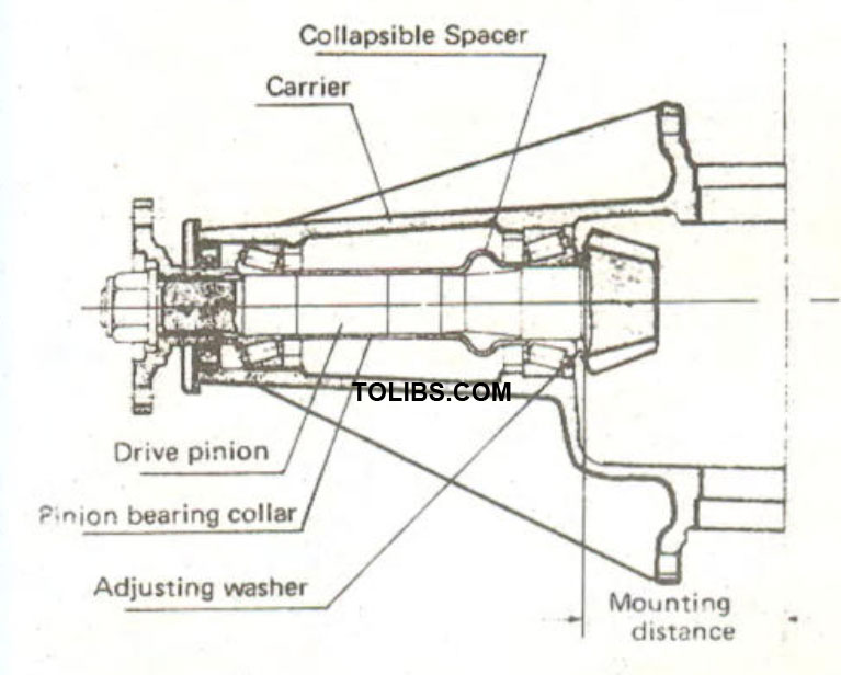
Sectional view of the drive pinion carrier to show the location of the parts.
Insert the dial gauge into the master gauge 49 0727 570 as shown in Fig. 5.6. and place the assembly into a surface plate. Push the dial gauge downwards until the pointer rotates approx. 3/4 turn clockwise and clamp in position. Set the dial gauge to “Zero" by turning the outer ring.
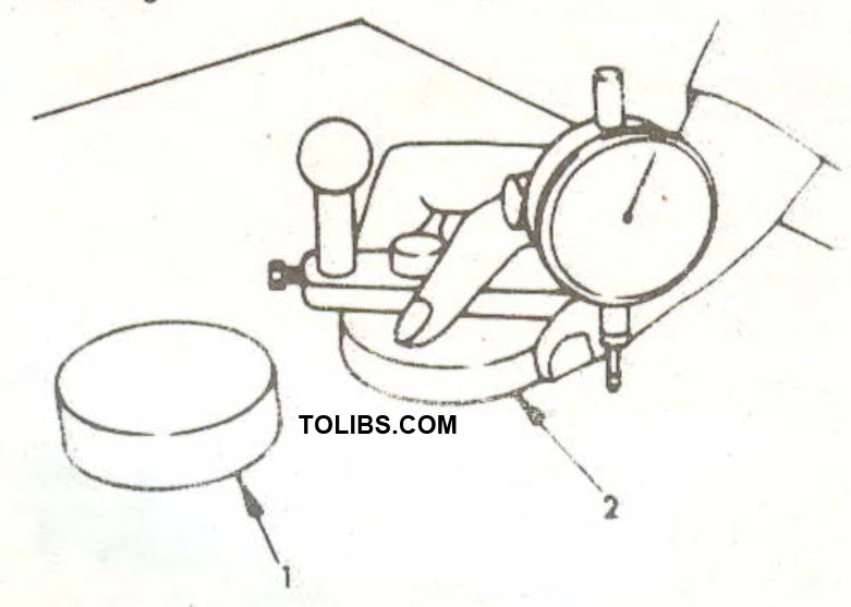
Using the gauge body (49 0727 570) to set the dial gauge to zero
Make sure that the differential bearing locating bores are free from dirt or burrs and fit the pinion bearing adjusting washer and the rear pinion bearing over the pinion shaft. Insert the pinion into the differential carrier and place the gauge block 49 0305 555 on top of the ground face of the pinion as shown in Fig. 5.8. Now place the master gauge on the gauge block so that the needle of the dial gauge rests in the lowest part of the differential bearinglocating bore. Read off the dial gauge and record the reading. Remove the pinion from the carrier, withdraw the pinion rear bearing and measure the thickness of the adjusting washer originally fitted for the measurement.
If the reading on the dial gauge shows a "+" value, this indicates that the original washer is too thick and should be replaced by a thinner washer. If the reading is replace the washer by a thicker washer. Before deciding on the thickness of the washer, place the master gauge once more on the surface plate and check if the "Zero" setting is still obtained.
![]()
The arrow shows the dummy bearing on the pinion shaft. The spacer should be placed between the bearing and the pinion head.
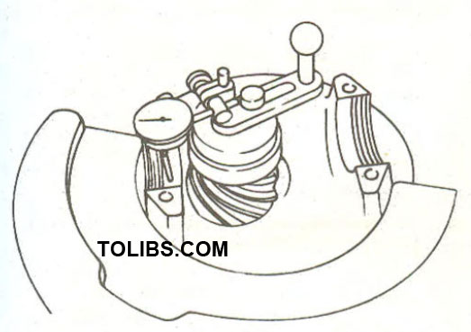
The dial gauge, the setting gauge and the gauge block (49 0305 555) in position in the differential carrier.
Now place the dummy bearing and the actual rear pinion bearing onto a surface plate and compare their height as shown in Fig. 5.9. If the actual bearing is higher than the dummy bearing, subtract the difference from the washer thickness. If the actual bearing is lower than the dummy bearing, add the difference to the washer thickness.

NOTE: To compensate manufacturing tolerances, the pinion is marked with a or " value, which is recorded in 1/100 millimetres. If the pinion is marked with a plus sign ("+"), for example "+2" = 0.02 mm - then subtract this amount from the thickness of the newly found pinion adjusting washer. Is the pinion mark a minus value ("-"), add the amount to the thickness of the pinion adjusting washer.
Place the determined adjusting washer onto the pinion shaft and press the pinion rear bearing over the shaft.
Adjusting the Pinion Bearing Pre-load
Drive in the pinion bearing cups into the differential carrier. Slide the collapsible spacer over the end of the pinion shaft and position the drive pinion shaft assembly into the carrier (as in Fig. 5.7.). Slide the pinion front bearing cover over the shaft and drive it in until it is fully seated. Grease the lips of the pinion oil seal and install the seal into the carrier. Fit the drive flange to the pinion shaft end and secure with washer and nut. Before tightening of the pinion nut attach a spring scale to the drive flange and turn the flange by pulling on the spring scale to check the drag of the pinion seal. Add the amount of the oil seal drag to the specified pre-load of 2.1 - 3.3kg (4.60 • 7.30 lb.), as this is the value for the bearing pre-load WITHOUT oil seal. Now tighten the pinion nut to a torque reading of 14 kgm (101 lb.ft.). DO NOT EXCEED THIS VALUE.
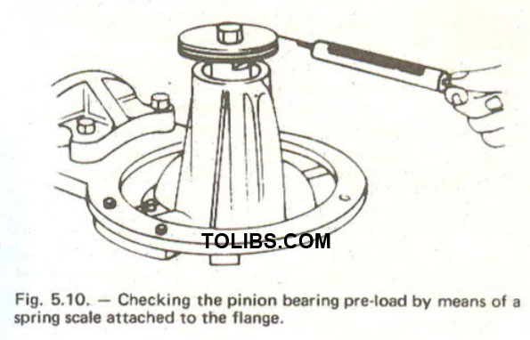
Re-check the bearing rotating torque as shown in Fig.5.10. If the indication is within the specification, the bearing pre-load adjustment is satisfactory. If the torque required to rotate the pinion drive is less than specified, tighten the pinion nut a little at a time, re-checking the torque frequently. NEVER OVER—TIGHTEN. The max. permissible tightening torque is 18 kgm (130 lb.ft.). If excessive pre-load has resulted from over-tightening of the nut, the collapsible spacer must be replaced. If on the other hand the tightening torque of the pinion nut is less than 14 kgm (101 lb.ft.) when the pre-load figurehas been reached, change the collapsible spacer.
Installation of the Differential
Place the assembled differential into the differential carrier and check that the marks for the backlash adjustment on the side of the pinion face and the crown wheel teeth are aligned with each other. As the adjusting nuts have rightrhand and left-hand thread, note the identification marks and fit each to its respective side. Fit the bearing caps in accordance with the marks made during dismantling and tighten the nuts fingertight. Now turn the adjusting nuts by means of wrench 49 0259 720 or a suitable peg spanner until the bearings are properly positionedin their outer races and all end-play is eliminated. There must, however, exist some backlash between crown wheel and the drive pinion. Slightly tighten one of each of the bearing cap nuts and adjust the backlash as follows:
Fit a dial gauge to the differential carrier so that the needle of the gauge rests at right angles on one of the crown wheel teeth. Check the backlash between the teeth at four or five different points. Adjust each of the adjusting nuts by the same amount until the mean value of the four or five measurements is between 0.17 - 0.19 mm (0.0067 - 0.0075 in.). After this operation adjust the differential bearing pre-load as follows:
By means of a large micrometer or a calliper or a large vernier gauge, measure the spread of the differential carrier at the positions shown in Fig. 5.11. The bearing pre-load is adjusted by tightening the adjusting nuts. Tightenthe nutsuntil the distance between the two faces shown in Fig. 5.11 is 185.428 mm (7.3004 in.). A tolerance of -0.072 mm (0.0028 in.) is permissible.
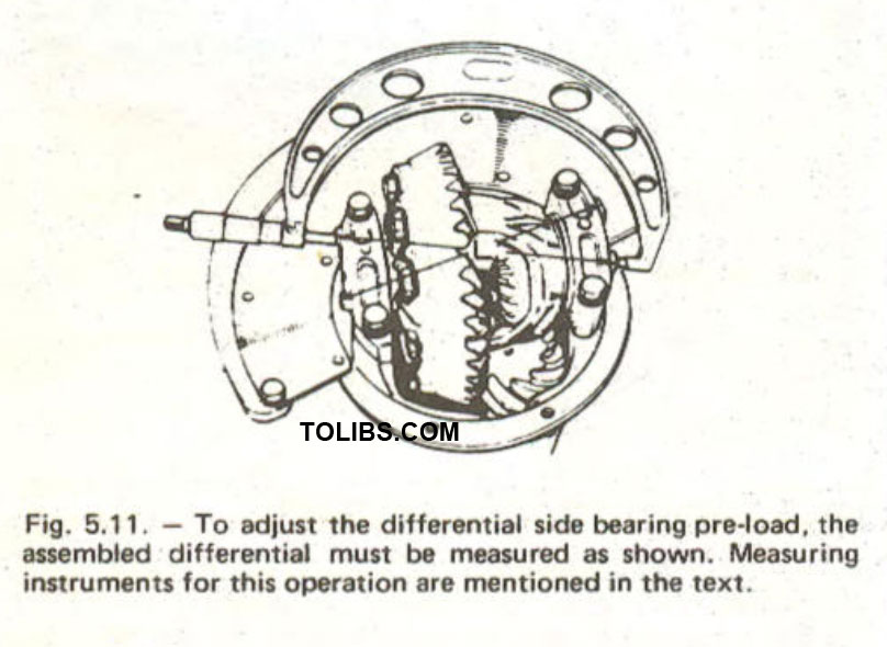
NOTE: When adjusting the pre-load, take care not to affect the setting of the backlash between the drive pinion and the crown wheel.
After correct adjustment, tighten the differential bearing caps to 4.0 kgm (30 Ib.ft.) and fit the lock plates for the adjusting nuts so that they engage into one of the holes of the nuts. Finally check the tooth marking of the crown wheel by smearing a little engineer's blue on the pinion teeth. Rotate the pinion whilst restraining the crown wheel with a block of wood. An ideal marking should be as shown in Fig. 5.12. The corrections possible are as follows:
To correct heel contact (towards outer edge), or face contact (high up on tooth flanks): Move the pinion towards the crown wheel. To correct toe contact (towards inner edge), or flank contact (low down in root of teeth): Move the pinion away from the crown wheel. All the above references are to the crown wheel markings. The differential must be re-adjusted if any of these corrections are carried out.
Two-Pinion Differential
Some final drive assemblies may have a slightly different differential. In this case the differential only has two pinion gears and the dismantling and assembling is therefore different. Dismantle as follows:
First drive out the securing pin fro the differential pinion shaft from the side shown in Fig. 5.13. Then drive out the differentia! pinion shaft, turn the differential gears by 90° and remove the pinion gears through the opening in the differential case. Differential side gears and thrust washers are now free for removal.
When assembling the differential, insert the two bevel gears through the openings so that they face each other by exactly 180°. Then turn the pinions by 90° until the pinion shaft holes in the differential housing are aligned with the holes in the bevel pinions. Insert the pinion shaft through the case and the pinions. Check the backlash between the side gears and pinions in the same manner as described previously for the 4-pinion differential and after adjusting, insert the pinion shaft securing pin from the opposite side of the differentia! housing to that shown in Fig. 5.13. Peen over the ends of the pin and secure it in position.
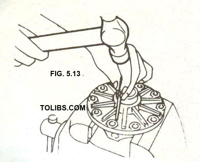
When dismantling the differential, drive out the differential pinion shaft securing pin from this side of the differential housing.
The remaining operations are carried out in the same manner as described for the 4-pinion differential. The crown wheel bolts should be tightened to the torque value given in Section 5.5. The bolts are fitted with lock washers.
Tightening Torque Values
- Propeller shaft to rear axle flange: 3.5 - 3.8 kgm (25.0- 27.0 Ib.ft.)
- Crown wheel to pinion: 5.5 - 6.5 kgm (40.0 - 47.0 Ib.ft.)
- Differential case halves: 2.5 -3.0 kgm (18-21 Ib.ft.)
- Differential bearing caps: 3.2 - 4.7 kgm (23 - 34 Ib.ft.)
- Drive flange to pinion: See Section 5.3.3.2.
- Propeller shaft to flange: 3.5 -3.8 kgm (25- 27 Ib.ft.)
- Rear axle to housing: 2.3 -2.7 kgm (17 - 19 Ib.ft.)
SHOCK ABSORBERS- REMOVAL AND INSTALLATION
With the rear of the vehicle resting on stands, remove the rear seat and undo the fasteners to take out the fuel tank partitioning board. Remove the nuts, washers and the rubber bush from the upper shock absorber end and remove the nuts and rubber mounting from the bottom end of the shock absorber. Remove the shock absorber.
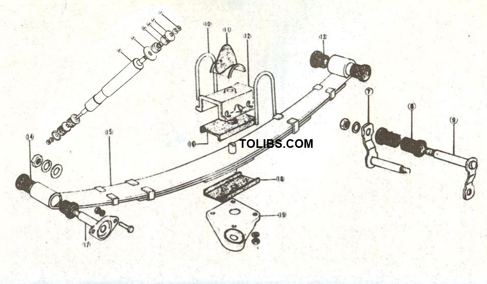
Fig. 6.1. - Exploded view of the rear suspension.
- Nut
- Washer
- Rubber bush
- Rubber bush
- Washer
- Rear shock absorber
- Spring shackle plate
- Rubber bush
- Spring shackle
- Spring "U" bolt
- Rebound rubber
- Spring retainer
- Rubber bush
- Rubber bush
- Rear spring
- Rubber pad
- Spring pin
- Rubber pad
- Spring clamp plate
To check the shock absorber, clamp the lower shock absorber eye into a vice in an upright position and work it up and down in its full length of travel several times. If a strong resistance is felt, the shock absorber is functioning properly. No resistance or sudden free movements requires the replacement of the shock absorber. The installation of the shock absorbers is carried out in reverse to the removal procedure. When tightening the shock absorber nuts, make sure that the stud is protruding by 11.1 mm (0.44 in.) at the upper end and by 5.5 mm (0.22 in.) at the lower end, above the face of the locknut. Fig. 6.2. shows a diagram of these dimensions.
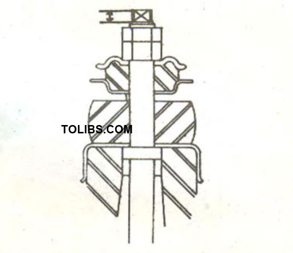
Fig. 6.2. - When tightening the upper mounting nuts of the shock absorbers, make sure to obtain the dimension shown by the arrows (see text above).
REAR LEAF SPRINGS- REMOVAL AND INSTALLATION
Refer to Fig. 6.1. for an exploded view of the rear suspension. To remove a spring, place the vehicle on stands and disconnect the lower mounting of the shock absorber. Remove the securing nuts from the "U" bolts and jack up the rear axle until it is clear of the spring. Remove the "U" bolts, spring pad and retainer. Remove the rear spring shackle after undoing the nuts and driving the shackle pins through their locations. Remove the bracket pin nut at the spring front end and unscrew the two bolts securing the bracket pin to the side of the frame. Pry off the bracket pin with a screwdriver as shown in Fig. 6.3.
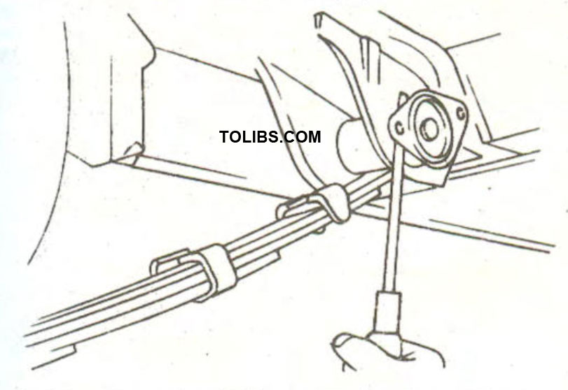
Fig. 6.3. - Removal of the front spring pin. A screwdriver is inserted as shown to pry out the pin.
Thoroughly clean the spring and check the spring leaves for wear, cracks and other damage. If necessary, replace the complete spring, mainly when the vehicle has covered a large mileage.
To refit, insert the two rubber bush halves (14 in Fig. 6.1.) into the front spring eye and insert the eye between the spring hanger. Insert the spring eye pin (17) from the outside and attach the nut, spring washer and washer from the inside without tightening the nut. Fit the bracket pin plate to the spring hanger. Insert the rubber bushes (8 and 13) at the rear end into the spring eye and the spring hanger and then drive in the shackle pins (7 and 9) from the sides shown in the illustration. Secure the shackle pins with the washers and nuts, without tightening the nuts completely.
Fit the spring retaining plate (19) with the rubber pad (18) from below the spring and lower the jack slowly, engaging the centre pin of the spring into the locating hole in the axle pad. Fit the upper rubber pad (16) and the rubber pad holder (12) on top of the spring and insert the "U" bolts (10) together with the rebound rubber (11) without damaging their threads. Tighten the "U" bolt nuts to a torque reading of 3.8 . 4.6 kgm (27 - 33 lb.ft.). The remaining operations are carried out in reverse order to the removal procedure. With the wheels of the car resting on the ground, tighten the spring pin nut and the spring shackle nuts to a torque setting of 4.0 kgm (30 lb.ft.). Before final tightening of the nuts, bump the car up and down several times in order to settle the suspension.