BOSCH L-Jetronic Injection Manual Mazda RX-8
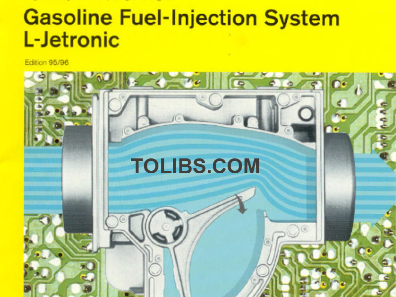
Gasoline Fuel-Injection System L-Jetronic
Since their introduction, Jetronic fuel injaction systems have proved themselves millions of times over under the harsh conditions of everyday driving. The on-going development of the control unit and the sensors has led from the D-Jetronic to the L-Jetronic, anc resulted in this fuel-injection system becoming even more precise
and reliable.
New circuitry for the evaluation of the sensor signals has led to more economical and more sophisticated engine operating characteristics. Thanks to the employment of the Lambda sensor, and the integration of the Lambda closed-loop control unit, the L-Jetronic can already comply today with the exhaust-gas legislation of tomorrow. This booklet tells you all you want Io know about the latest developments in theL-Jetronic.
Combustion in the spark-ignition engine
The spark-ignition or Otto-cycle engine
Principles
The spark-ignition or Otto-cycle1) engine is a combustion engine with externally supplied ignition which converts the energy contained in the fuel into kinetic energy.
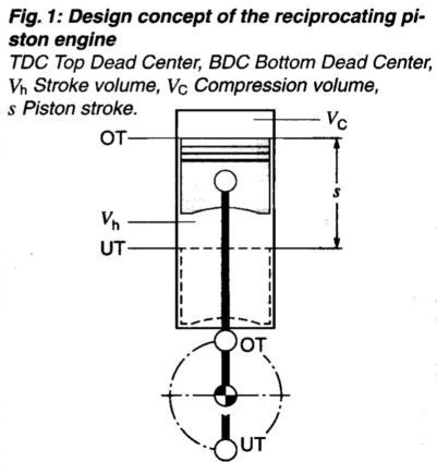
The spark-ignition engine employs a mixture-formation apparatus located outside the combustion chamber to form an airfuel mixture (based on gasoline or a gas). As the piston descends, the mixture is drawn into the combustion chamber, where it is then compressed as the piston moves upward. An external ignition source, triggered at specific intervals, uses a spark plug to initiate combustion in the mixture. The heat released in the combustion process raises the pressure within the cylinder, and the piston pushes down against the crankshaft, providing the actual work energy (power). After each combustion stroke the spent gases are expelled from the cylinder and a fresh air-fuel mixture is drawn in. In automotive engines this exchange of gases is generally regulated according to the fourstroke principle, with two crankshaft revolutions being required for each complete cycle.
The four-stroke principle
The four-stroke spark-ignition engine employs gas-exchange valves to control the gas flow. These valves open and close the cylinder’s intake and exhaust tracts:
- 1st stroke: Induction
- 2nd stroke: Compression and ignition
- 3rd stroke: Combustion and work
- 4th stroke: Exhaust.
Induction stroke
Intake valve: open,
Exhaust valve: closed,
Piston travel: downward,
Combustion: none.
The piston’s downward motion increases the cylinder’s effective volume and pulls n fresh air-fuel mixture through the open intake valve.
Compression stroke
Intake valve: closed,
Exhaust valve: closed,
Piston travel: upward,
Combustion: initial ignition phase.
As the piston travels upward, it reduces the cylinder’s effective volume and compresses the air-fuel mixture. Just before the piston reaches top dead center (TDC), the spark plug ignites the compressed air-fuel mixture to initiate combustion. The compression ratio is calculated with the stroke volume Vh and compression volume Vc: E = (Vh+Vc)/Vc.
Compression ratios e range between 7 and 13 to one, depending upon engine design. Increasing the compression ratio in a combustion engine enhances its thermal efficiency and provides more effective use of the fuel. For instance, raising the compression ratio from 6:1 to 8:1 produces a 12% improvement in thermal efficiency. The latitude for such increases is restricted by the knock (or preignition) limit. Knock refers to uncontrolled mixture combustion characterized by a radical increase in pressure. Combustion knock leads to engine damage. Appropriate fuels and combustion-chamber configurations can be employed to shift the knock limit toward higher compression ratios.
Power stroke
Intake valve: closed,
Exhaust valve: closed,
Piston travel: upward,
Combustion: combustion completed.
When the spark at the spark plug ignites the air-fuel mixture, the gas mixture combusts and the temperature increases. The pressure level in the cylinder also increases, pushing the piston downward. The force from the moving piston is transferred through the connecting rod and to the crankshaft in the form of work this is the actual source of the engine’s power. Output rises as a function of increas ed engine speed and higher torque (P = M-w).
A transmission incorporating various conversion ratios is required to adapt the combustion engine's power and torque curves to the demands of actual vehicular operation.
Exhaust stroke
Intake valve: closed,
Exhaust valve: open,
Piston travel: upward,
Combustion: none.
Operating cycle of the four-stroke spark-ignition engine
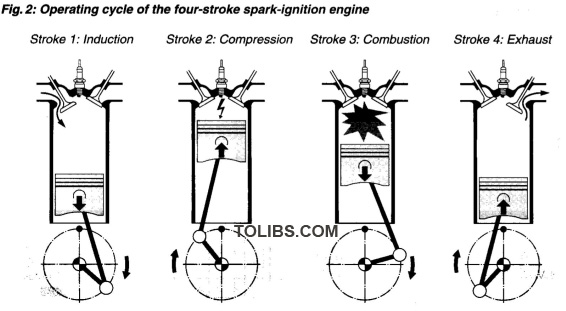
As the piston travels upward, it pushes the spent gases (exhaust gases) out through the open exhaust valve. The cycle is then repeated. The periods when the valves are open overlap by a certain degree; this improves the gas-flow and oscillation patterns for enhanced cylinder filling and scavenging.
Mixture formation
Overview
Parameters
Air-fuel mixture
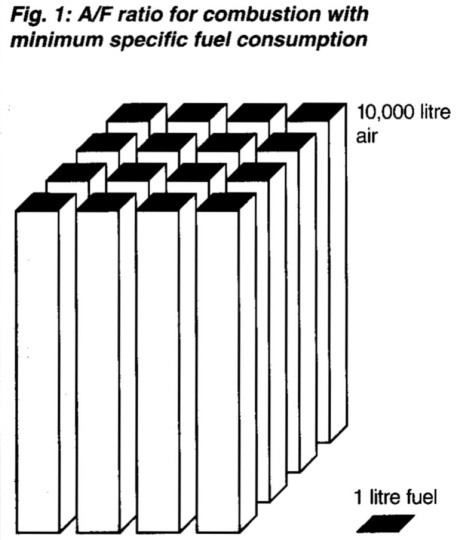
The spark-ignition engine requires a specific air/fuel ratio (A/F ratio) in order to operate. The theoretical ideal for complete combustion is 14.7:1, and is referred to as the stoichiometric ratio. Mixture corrections are required to satisfy the special engine demands encountered under particular operating conditions.
The specific fuel consumption of the spark-ignition engine is largely a function of the A/F ratio. In theory, excess air is required to achieve the minimum fuel consumption that would result from complete combustion. In practice, however, latitude is restricted by factors such as mixture flammability and limits on the time available for combustion.
On contemporary engines, minimum fuel consumption is encountered at an A/F ratio corresponding to approximately 15...18 kg air for each kg of fuel. In other words, about 10,000 litres of air are required to support combustion in one litre of fuel (Figure 1).
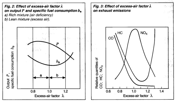
Excess-air factor
The excess-air factor (or air ratio) A has been chosen to indicate how far the actual air-fuel mixture deviates from the theoretical optimum (14.7:1).
- A = Induction air mass/air requirement for stoichiometeric combustion
- 2 = 1: The induction air mass corresponds to the theoretical requirement.
- 2 < 1: Air deficiency, rich mixture. Increased output is available at 2 = 0.85...0.95.
- 2 > 1: Excess air (lean mixture) in the range 2 = 1.05...1.3. Excess-air factors in this range result in lower fuel consumption accompanied by reduced performance.
- 2 > 1.3: The mixture ceases to be ignitable. Ignition miss occurs, accompanied by pronounced loss of operating smoothness.
Spark-ignition engines achieve their maximum output at air-deficiency levels of 5...15% (A = 0.95...0.85), while minimum fuel consumption is achieved with an air excess of 10...20% (A = 1.1...1.2). A = 1 provides optimum idling characteristics. Figures 2 and 3 illustrate the effect of the excess-air factor A on output, specific fuel consumption and exhaust emissions. It will be noted that no single excessair factor can simultaneously generate optimal response in all areas. Air factors ranging from A 0.9...1.1 provide the best results in actual practice.
Once the engine has reached its normal operating temperature, it is essential that A = 1 be maintained to support subsequent exhaust treatment with a threeway catalytic converter. The preconditions for satisfying this requirement are precise determination of the induction-aiquantity accompanied by an arrangement capable of providing exact fuel metering. To ensure a satisfactory combustion process, precise fuel metering must be accompanied by homogeneous mixture formation. The fuel must be thoroughly atomized. If this condition is not satisfied, large fuel droplets will form along the walls of the inlet tract, leading to higher HC emisssions.
Adapting to specific operating conditions
Certain operating states will cause the fuel requirement to deviate considerably from that required by a stationary engine at normal operating temperature the mixture must be corrected accordingly.
Cold starts
During cold starts, the relative amount of fuel in the mixture decreases; the mixture “goes lean.” Inadequate blending of fuel and air in the intake mixture, low fuel vaporization and condensation on the walls of the intake tract due to the low temperatures, all contribute to this phenomenon. To compensate, and to assist the cold engine in “getting started,” supplementary fuel must be made available for starting.
Post-start phase
After starts at low temperatures, supplementary fuel must be provided to enrich the mixture until the combustion chamber heats up and the mixture formation within the cylinder improves. The richer mixture also increases torque to provide a smoother transition to the desired idle speed.
Warm-up phase
The starting and post-start phases are followed by the engine’s warm-up phase. In this phase the engine still requires a richer mixture, as the cylinder walls are still cool, and a portion of the fuel continues to condense on them. Since the quality of mixture formation drops along with failing temperatures (due to less effective mixing of air and fuel, and large fuel droplets), condensation forms in the intake manifold, where it remains until it is vaporized as temperatures increase. These factors make it necessary to provide progressive mixture enrichment in response to decreasing temperatures.
Part-throttle operation
During part-throttle operation priority is assigned to adjusting the mixture for minimum fuel consumption. The threeway catalytic converters required to meet stringent emissions limits are making it increasingly important to control the systems for 2 = 1.
Full-throttle operation
When the throttle valve has opened to its maximum aperture, the engine should respond by providing its maximum torque/output. As Figure 2 indicates, this necessitates enrichening the air-fuel mixture to 2 = 0.85 . . . 0.90.
Acceleration
When the throttle valve opens suddenly, the air-fuel mixture responds by leaning out briefly. This is due to the fuel’s restricted vaporization potential at higher manifold vacuum levels (increased tendency to form fuel layers on intaketract walls). To obtain good transition response, the mixture must be enriched by an amount which varies according to engine temperature. This enrichment provides good acceleration response.
Trailing-throttle (overrun) operation
The fuel-metering process can be inter rupted on trailing throttle to reduce fuel consumption during descents and under braking. Another advantage is the fact that no harmful exhaust emissions are generated in this operating mode.
High-altitude adjustment
Increases in altitude (as encountered during alpine operation) are accompanied by a reduction in air density. This means that the intake air being drawn into the engine at high altitudes displays a lower mass per unit of volume. A system which fails to adjust the mixture accordingly will supply an excessively rich mixture, and the ultimate result will be higher fuel consumption and increased exhaust emissions.
Mixture-formation systems
The function of the carburetor or fuelinjection system is to supply the engine with the optimum air-fuel mixture for instantaneous operating conditions. For some years now, fuel injection has represented the preferred method, a development accelerated by the advantages that injecting the fuel provides in the areas of economy, performance, driveability and low exhaust emissions. Fuel injection can be applied for extremely precise metering, supplying exactly the correct amount of fuel for given operating and load conditions while simultaneously ensuring minimum levels of exhaust emissions. The composition of the mixture is controlled to maintain low emissions.
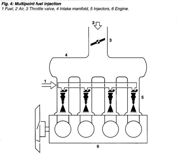
Multipoint fuel injection
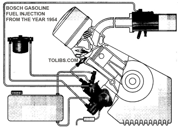
Multipoint injection supplies the ideal starting point for meeting these objectives. The multipoint injection system uses a separate injector to inject the fuel directly through the intake valve at each individual cylinder. Examples of this type of design are the KE- and L-Jetronic in their various individual configurations (Figure 4).
Mechanical injection system
K-Jetronic is a mechanical injection system in widespread use. This driveless system injects the fuel in a continuous process.
Combined mechanical and electronic injection system
KE-Jetronic is an expanded version of the basic K-Jetronic system. It monitors an extended range of operating data for electronic open-loop control of auxiliary functions to provide more precise fuel metering under varying engine operating conditions.
Electronic injection systems
Electronically-controlled injection systems use electro-magnetic injectors to inject the fuel intermittently.
Examples: L-Jetronic, LH-Jetronic, and the Motronic integrated fuel-injection and ignition system.
Single-point (throttle-body, central) fuel injection
Single-point fuel injection describes an electronically-controlled injection unit featuring an electromagnetic injector located directly above the throttle valve. This injector sprays fuel into the intake manifold in an intermittent pattern. Mono-Jetronic is the brand name of the Bosch single-point injection system (Figure 5).
Advantages of fuel injection
Reduced fuel consumption
This system monitors all essential engine operating data (e.g., engine speed, load, temperature, throttle-valve aperture) for precise adaptation to stationary and dynamic operating conditions, thereby ensuring that the engine receives only the amount of fuel that it actually requires under any given circumstances.
The story of fuel injection
The story of fuel injection extends back to cover a period of almost one hundred years. The Gasmotorenfabik Deutz was manufacturing plunger pumps for injecting fuel in a limited production series as early as 1898. A short time later the uses of the venturi-effect for carburetor design were discovered, and fuel-injection systems based on the technology of the time ceased to be competitive. Bosch started research on gasolineinjection pumps in 1912. The first aircraft engine featuring Bosch fuel injection, a 1200-hp unit, entered series production in 1937; problems with carburetor icing and fire hazards had lent special impetus to fuel-injection development work for the aeronautics field. This development marks the beginning of the era of fuel injection at Bosch, but there was still a long path to travel on the way to fuel injection for passenger cars.
1951 saw a Bosch direct-injection unit being featured as standard equipment on a small car for the first time. Several years later a unit was installed in the 300 SL, the legendary production sports car from Daimler-Benz. In the years that followed, development on mechanical injection pumps continued, and...In 1967 fuel injection took another giant step forward: The first electronic injection system: the intake-pressurecontrolled D-Jetronic! In 1973 the air-flow-controlled L-Jetronic appeared on the market, at the same time as the K-Jetronic, which featured mechanical-hydraulic control as well as an air-flow sensor. 1979 marked the introduction of a new system: Motronic, featuring digital processing for numerous engine functions. This system combined L-Jetronic with electronic program-map control for the ignition. The first automotive microprocessor!
In 1982, the K-Jetronic model became available in an expanded configuration including an electronic closedloop control circuit and a Lambda oxygen sensor the KE-Jetronic. These were joined by Bosch MonoJetronic in 1983: This particularly cost-efficient single-point injection unit made it feasible to equip small vehicles with Jetronic. 1991 saw Bosch fuel-injection units performing in more than 37 million vehicles throughout the world. 5.6 million engine-management systems were delivered in 1992. Of this number, 2.5 million were Mono-Jetronic and Mono-Motronic systems, with 2 million Motronic systems being supplied within the same period. Today fuel-injection systems have become an essential automotive component.