How to Modify Your Mazda Rx-7
D.I.Y to Modify Your Mazda Rx-7
High-performance mods to 12A & 13B rotary engines. Clutch, transmission & rear-axle recommendations. Suspension & brake preparation & tuning. Air dams, spoilers, fender flares & more. Complete parts list.
Dave Emanuel began his careerin journalism in 1970 when Car Craft magazine published his first article. Since then, his byline has appeared on over 750 feature articles in magazines such as Road & Track, Motor Trend, Circle Track, Popular Science, Home Mechanix, GEO, Sports Car Illustrated, Automobile Quarterly, InnAmerica and Regency. He has also written three books.
A thorough knowledge of a subject is required before someone can write authoritatively about it and Dave gained his knowledge about automobiles the old fashioned way-he broke them. Even before he was of legal driving age, he had a shattered transmission behind him. After learning how to repair his own damage, he routinely helped his friends who were equally adept at finding the stress limits of various kinds of steel alloys.
Actually, most of the repair work that Dave had to do was caused by a physical problem-an extreme amount of force applied by the right foot. With such an affliction, it was only natural that Dave would wind up on a race track. Over the years, he has been involved in drag racing, autocrossing and road racing and his experiences have added to his knowledge of cars and the techniques that improve performance and handling.
The marriage of journalism and automobiles came about when Dave set a track record with a 428 Mustang and decided to chronicle his efforts. He was then working as a systems analyst for a computer company, but he continued writing about high-performance cars and modifications. After dabbling in journalism on a part-time basis for several years, Dave left the computer field to devote full time to writing. In a relatively few years, he has established himself as one of the country’s leading independent automotive journalists.
Jim Downing began racing in 1963, behind the wheel of an Elva Courier. For several years, his participation was limited to SCCA club events primarily in the Atlanta, Georgia area. In his second year of competition, Jim drove a Formula Vee machine and did well enough to be invited to the first SCCA Runoffs, then held in Riverside, California. From the outset of his racing career, Jim never intended to become more than a hobby racer competing in the amateur ranks. But in 1974, after growing dissatisfied with club racing, he made the jump to professional road racing when he competed in IMSA’s (International Motor Sports Association) Champion Spark Plug Series. And since 1979, he has been a full-time road racer. A consistent front-runner, Jim placed second in the Champion Spark Plug Series in 1980, and won the championship in 1981. In 1982, he moved on to the GTU category and promptly won that series championship.
1983 was a year of transition for Jim, co-driver John Maffucci and the entire Downing/Atlanta team. While concentrating on development of a totally new car for IMSA’s Prototype (GTP) class, Jim continued to race hisGTU car and just missed winning a second championship. With the new car-built in accordance with the rules for the World Endurance Championship 700 kilogram class-completed, Jim campaigned in GTP during 1984. In essence, he had a Camel Lights car, even though the class did not yet exist. However, when Camel Lights was introduced in 1985, the Downing/Atlanta team was ready. Jim won the championship in both 1985 and 1986.
Jim’s automotive background began when he was a youngster his father owned several auto-import dealerships in Atlanta. During college, Jim ran a repair shop specializing in English cars. Following graduation from Georgia Institute of Technology, he followed in his father’s footsteps by opening an imported car dealership. He has also been involved in auto-parts retailing, but racing has been and is, his prime interest.
Another Fact-Filled Automotive Book from HPBooks
NOTICE: The information contained in this book is true and complete to the best of our knowledge. All recommendations on parts and procedures are made without any guarantees on the part of the author or HPBooks. Because the quality of parts, procedures and methods are beyond our control, author and publisher disclaim all liability incurred in connection with the use of this information.
Thanks: To Craig Caldwell and John Jelenek of Hill & Knowlton, Jim Mederer of Racing Beat and Royce Branch of the RX-7 Club of America for their help in supplying information, photos and drawings. Special thanks to my wife Kathy for her help and understanding and to Rick Engman for his patient assistance during the writing and review of the original manuscrip
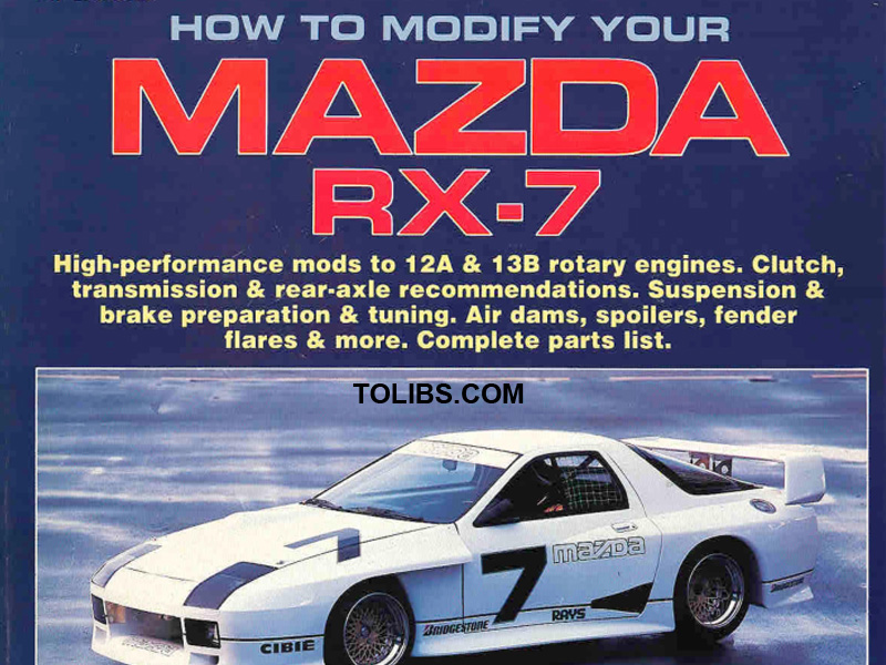
Mazda's RX-7, introducedin 1978, was the car that put the rotary engine on the map. Sports-car aficionados have found the car to offer exciting performance, economical operation and excellent reliability. What else could you ask for?
As the automobile foundered in its embryonic state, inventors and designers experimented with various types of power-producing devices. Piston engines, steam engines and electric motors all served in man’s quest to perfect a self-propelled vehicle. Although the piston or reciprocating engine was crude and not terribly efficient, it quickly became the dominant automotive powerplant. For in spite of its shortcomings, the reciprocating engine is comparatively easy to build and service, does not rely on batteries that require periodic recharging, and does not require that the driver wait for water to boil before he or she can drive off.
THE BEGINNING OF ROTARY POWER
Although reciprocating-type internalcombustion automobile engines date back to 1876, when Nikolaus Otto of Germany perfected his design, development of the rotary engine actually predates Otto. However, the earliest efforts to develop practical rotary mechanisms were centered around pumps and compressors rather than engines. (In 1588, Agostino Ramelli designed a rotary piston water pump.) James Watt, whose name is associated with development of the piston-type steam engine, also took out several patents covering rotary steam engines. Between 1772 and 1782, Watt designed a number of rotary steam engines. However, insufficient rotor-tohousing sealing prevented these eng ines from being put to practical use.
Development of rotary steam engines continued and they became a viable source of power by the mid-19th century. But, it wasn’t until 1908 that the internal-combustion rotary engine was designed. The brain child of a British engineer named Umpleby, it was essentially a conversion of the rotary steam engine patented by John F. Cooler in 1903. Although his intentions were undoubtedly in earnest, Umpleby nevei fully developed his idea.
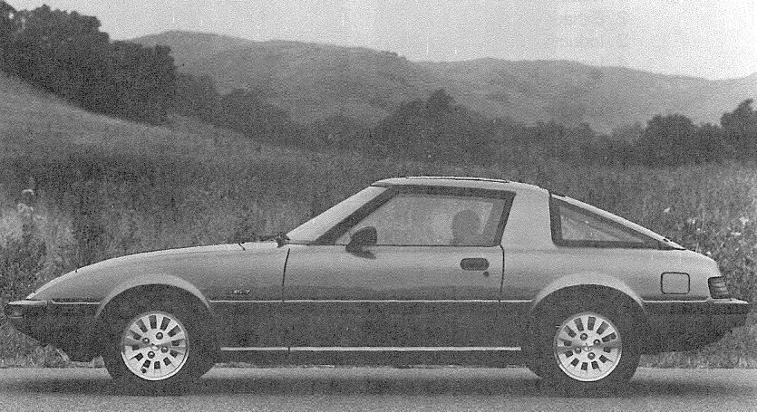
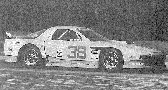
The Camel Lights GTP race car, campaigned by Jim Downing andco-driver John Maffucci, represents the epitome in naturally aspirated rotary-engine development. The Downing/Atlanta team won the IMSA Camel Lights championship in both 1985 and '86.
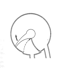
James Watt of steam-engine fame was one of the early experimenters who dabbled will? rotary power. He invented a rotary stoam engine in 1759. Drawing courtesy Mazda.
Roger Mandeville introduced his 1986 IMSA GTO RX-7 at the season finale at Daytona. The engine, a three-rotor model that produced over 450 HP, featured an electronic management system.. Obviously, rotary engines have come a long way since the RX-7 was introduced.
Enter Felix Wankel - Even in the 1938 design of Dimitri Sensaud de Lavou, sealing was terribly ineffective. In spite of these problems there never seemed to be a lack of inventors willing to carry the torch for rotary power. And when Dr. I Wankel of West Germany picked up the torch, he carried it to new heights. In 1951, Wankel devised a rotary compressor that was used as a supercharger on an NSU motorcycle, built specifically to set speed records. The rotary compressor served as a springboard for development of a truly viable rotary internal-combustion engine.
Were it not for madman Hitler’s rise to power, Wankel’s development of the rotary engine might have come to fruition considerably sooner. Wankel had been involved in the uncovering of an embezzlement scheme by the Socialist party. When Hitler became State Chancellor, Wankel was labeled a traitor to the party. But he was lucky. Wankel was only imprisoned for several months, not sent to the gas chamber.
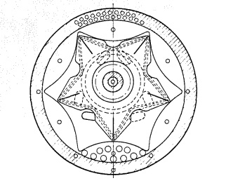
Rotary engine according to Sensaud de Lavou: 1938 design had some merit, but couldn't be putin to production because of sealing and lubrication problems. Drawing courtesy Mazda.
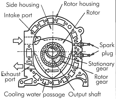
Basic construction of a rotary engine withkey components identified. Drawing courtesy Mazda.
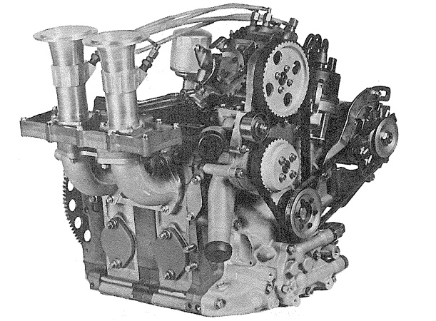
The 13G three-rotor engine was installed in the Mazda 757 GTP race cars that competed at Le Mans. Displacing 1962cc's, by virtue of three 654cc chambers, this is the largest rotary engine to be installed in a race car.
Wankel had applied for a patent on a two-rotor rotary engine on September 24, 1934. But after being released from prison, he became involved in various government-sponsored projects aimed at improving the performance of piston aircraft engines. It wasn’t until 1951, when Wankel teamed with NSU, that rotaryengine development got rolling again. With NSU resources at his avail, Wankel began converting his rotary air pump to an internal-combustion engine. And on February 1, 1957, his DKM-54 test engine ran under its own power. (DKM is an abbreviation of Drehkolben motor, the German word for rotary-piston engine.)
As originally developed, Wankel’s rotary included both an inner and outer rotor inside an external case. This arrangement added both cost and weight, so Dr. W. G. Froede and the engineering staff at NSU redesigned the DKM engine. They replaced the outer rotor with a stationary rotor housing. This design was known as the Kreiskolbenmotor (KKM).
Thefirst KKM engine, a 125cc singlerotor model was first tested in 1957. It weighed only 37 pounds with a cast-iron housing and 23 pounds with an aluminum housing. More importantly, it greatly simplified the intake and ignition systems. The KKM-125 was the precursor of today’s rotary engine as produced by Mazda. In Wankel’s DKM engine, the sparkplugs were in the rotor faces and the intake mixture was brought in through the eccentric shaft.
Following the KKM-125, Froede build a 250cc version for further development. The first endurance testing took place in 1959 and in 1960, the engine passed its first 1,000-hour durability test. It also registered a maximum of 44 HP at 9,000 rpm. The KKM-250 ultimately led to development of the KKM-612 tworotor engine that is widely known as the NSU Ro-80.
With only 60-70% of the parts foundin a piston engine, arotary is simpler, more durable and more reliable. Drawing courtesy Rotary Rocket.
Mazda Rotary
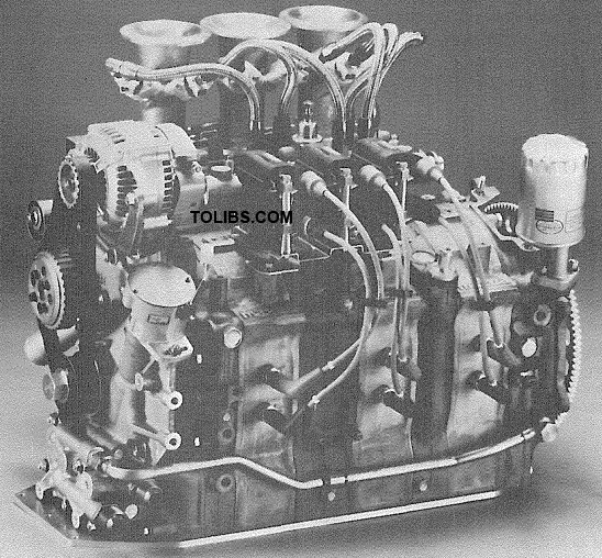
When BF Goodrich decided to campaign a car in IMSA's GTP category and in World Endurance Championship, engine reliability was a top priority. A Mazda 13B was selected and installed in a Lola T616 chassis. Engine produced 300HP at 8500 rpm and weighed a mere 231 pounds.
MAZDA-THE ROTARY ROCKET
In spite of all the Wankel engine development undertaken by NSU, the rotary never achieved broad viability until Toyo Kogyo (Mazda) bought a license to manufacture Wankel gasoline engines of 200 HP or less. However, Mazda wasn’t the first licensee; Yanmar Diesel, also of Japan, was licensed two days before Toyo Kogyo (1961). Other companies, including Daimler-Benz, Alfa-Romeo, Nissan, General Motors, Suzuki, Curtiss-Wright, Porsche and even Rolls Royce, also purchased licenses to produce rotary engines of various power ratings. However, Mazda is the company that truly put the rotary engine on the map.
Mazda began developing its own version of the Wankel shortly after obtaining its manufacturing license from NSU. Under the leadership of Kenichi Yamamoto, who was then manager of rotary engine development and is now president of Mazda, the original NSU design was refined over a five-year period.
The first Mazda prototype rotary engine, a single-rotor model, was at best disheartening. It vibrated badly at low speeds and consumed prodigious amounts of oil. A second prototype was little better and Mazda engineers soon determined that a twin-rotor engine would be required if the rotary was ever to be used in a passenger car.
After building a twin-rotor prototype and making countless modifications, Mazda engineers finally got the rotary whipped into shape. The first Mazda rotary engine released for public consumption finally appeared in the 1967 Mazda Cosmo Sports.
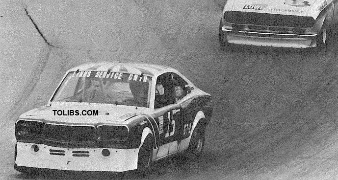
Rotary engines are strong competitors in a variety of SCCA classes. This RX-3, driven by Chris Dembs, won the GT-2 class at the 1982 runoffs at Road Atlanta.
The first Mazda rotary-engined vehicle hummed its way to the United States in the RI00 passenger car which debuted in 1971. In 1972, the RX-2, with a 12A engine was introduced and the rotan revolution was under way. Engine size was increased in 1974 when the 13B made its debut.
In the Mazda scheme of things, “12A” represents a powerplant with a nominal 1200cc, or 70 cubic inch (in.3), displacement; “13B”, as might be expected, indicates a nominal 1300cc (80 in.3) engine. The 13B’s additional displacement is achieved by virtue of wider rotors and rotor housings. Housing widths are 70mm for 12A and 80mm for 13B engines. In computing these displacements, a rotary is considered a “two-cylinder” engine with each “cylinder” (rotor housing) having a displacement of 654cc in the case of a 13B and 573cc in the case of a 12A.
While rotary engines were reasonably successful in Mazda RX-2, RX-3 and RX-4 automobiles, and in the rotary pickup truck, the engine rocketed to popularity when the RX-7 sports car debuted in 1978. Over the years, the continuing refinements made by Mazda haveeliminated virtually all of the drawbacks associated with early rotary engines.
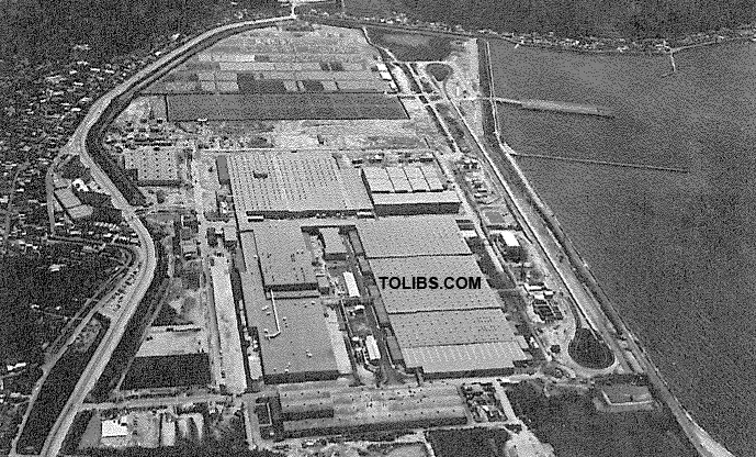
Although Mazda's headquarters is in Hiroshima, the company has a production facility in Hofu City, about 56 miles away. The plant site covers 198 acres.
INNER WORKINGS
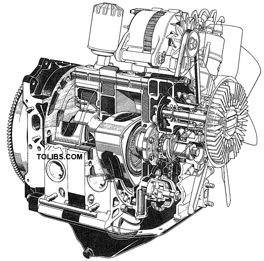
With comparatively few moving parts, the operation of a rotary engine is relatively simple. Rather than pistons, connecting rods and a crankshaft, a rotary utilizes rotors revolving around an eccentric -also called output-shaft as a means of converting the force of combustion into shaft power. In a two-rotor engine, both rotors revolve around a single eccentric shaft, which has a bearing journal and stationary gear for each rotor.
Although each of the three working chambers are completely separated from one another, there are times during the exhaust cycle when the rotor apexes are positioned in the middle of the intake and exhaust ports. When this occurs, exhaust from one working chamber can flow into the intake charge in another chamber. Due to port positioning, the exhaust gasses can still be under considerable pressure during this port-overlap period. Consequently, as explained in Chapter 2, a free-flowing exhaust system is critical to rotary-engine performance.
Port Configurations-Within the realm of Mazda rotaries, the intake ports on production engines are in the end and intermediate housings; the exhaust ports are in the rotor housings. Race engines utilize special rotor housings that contain both an intake and an exhaust port. These engines are commonly referred to as being of the peripheral intake-port variety whereas the production powerplants are of the side intake-port persuasion. (Exhaust ports in Mazda rotaries are always peripheral.)
With its large cross-section and straight, direct entry, the peripheral intake port is understandably more efficient than its side-port counterpart. But, in addition to its shape, its position and height are also influential with respect to intake-charging efficiency. On the negative side of the ledger, due to its position and height, a peripheral intake port is open longer than a side intake port. This leads intaketo aand longer exhaust overlapare period open - where simultaneously, As overlap is increased, so is the amount of exhaust dilution of the
intake charge. The situation is analogous to that of a piston engine with a longduration camshaft. In both cases, the extended-overlap period is acceptable at high rpm, but leads to reduced torque and poor driveability at low engine speeds.
Although the side-port configuration restricts high-speed power potential, it is much more suitable for passenger-car use. With entry through the end and intermediate housings, rather than through the rotor housing, intake-port timing is compatible with engine speeds found in passenger- and sports-car operation.
In terms of increasing torque and horsepower for high-performance ami racing applications, many of the principles that apply to a reciprocating engine are applicable to a rotary. Obviouslv. execution of those principles requires an approach unique to the rotary engine which is why this is but the first chapter.
A variation on the side intake-port theme is the bridge port. This involve greatly enlarging the port while leaving a thin bridge of material between the original contour and the newly ported area to support the seals. Bridge porting gives opening and closing timing that is similar to, but slightly shorter than that achieved with peripheral ports. Bridge porting b used instead of peripheral ports when class rules specify original-production equipment must be retained.
Exhaust
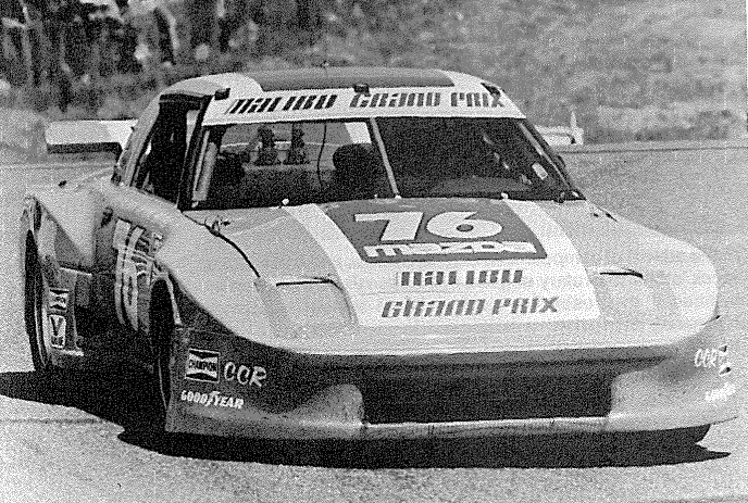
For street and racing, rotary-engine exhaust noise is always a problem. Unless you enjoy collecting traffic citations, a racing type exhaust system, such as the one used on this championship GTU racer, shouldn’t even be considered for use on a street car. An interesting a side, this car, designed by David Downing, has won four GTU championships 1982 with Jim Downing at the wheel, 1984 and 1985 with Jack Baldwin and 1986 with Tom Kendall.
It’s only logical when delving into the innermost secrets of an internal combustion engine that the explanation should follow the same event sequence as that of its subject-intake, compression, power, exhaust. So why on earth, you are no doubt wondering, does Chapter 2 deal with the exhaust rather than intake cycle?
No, you guessed wrong. The author hasn’t developed a terminal case of brain fade. Exhausting spent gasses may be the last cycle of the combustion process, but when dealing with a rotary engine, it is of paramount importance.
Restrictions in the exhaust system will choke the life out of the healthiest rotary powerplant. In fact, the need for a freeflowing exhaust becomes increasingly more critical with every power-raising modification. Consequently, when modifiyiing a Mazda rotary engine, the exhaust system is the place to start, not end. So, there is some logic at work here after all.
Intake-Charge Dilution- A restrictive exhaust system has a detrimental effect on the performance of any type of internal-combustion engine. But with a rotary powerplant it is especially harmful because the incoming charge can be diluted by the gasses from two exhaust cycles rather than one. Internal combustion is internal combustion irrespective of whether the engine involved is of the reciprocating or rotary persuasion. But the rotary is unique because its combustion chambers move. As the rotor spins through its assigned route, it pulls the intake charge in, compresses the fresh mixture while moving it over to the sparkplugs, then delivers the spent gasses to the exhaust port.
The gasses in one chamber are not completely eliminated before gasses from the succeeding chamber are brought to the exhaust port. And during the time the rotor apex is across the port, the highpressure exhaust gas from the following chamber can travel into the leading chamber and up to the intake port. This double dose of exhaust gas is obviously detrimental to the power-producing capabilities of the intake mixture, but the situation is made worse because the gasses in the second chamber are at maximum pressure when the apex clears the exhaust port.
Consequently, if flow through the exhaust system is impeded to a significant degree, it’s far more serious than it would be with a reciprocating engine, where the gasses remaining in the combustion chamber are simply residual and relatively benign. In a rotary, a restrictive exhaust system results in both residual and high-pressure exhaust gas-from the following chamber- interfering with the intake system.
The situation is roughly analogous to a two-cylinder, four-cycle reciprocating engine with both cylinders served by a single exhaust port. If cylinder number-1 were in its overlap period- where both intake and exhaust valves are open- and the exhaust valve of cylinder number-2 opened, its high-pressure exhaust gas could enter cylinder number-1- because of the single exhaust port-and play havoc with the incoming air/fuel mixture. Naturally, a highly restrictive exhaust system would aggravate the situation- just as it does in a rotary. As exhaust back-pressure increases, a greater percentage of the high-pressure exhaust-from the following chamber is channeled into the chamber receiving a fresh intake charge. That results in a decrease in intake-charge volume and a corresponding drop in power output.
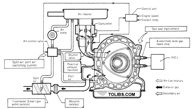
Air and exhaust gas-flow through catalytic-converter-equipped exhaust system. Drawing courtesy Mazda.
Power losses caused by restrictive exhaust systems aren’t as great in reciprocating engines because each cylinder has its own exhaust port. And highperformance and race engines are fitted with headers that keep the exhaust pipes from each cylinder separated for some 17 distance. In instances where tracts from adjacent cylinders completely isolated-as in utilizing Siamesed exhaust exhaust can’t be engines ports power output is less than optimum.
With stock-type reciprocating engines where the exhaust manifolds are essentially a single collecting chamber, valve opening and closing times can be easily altered to minimize the negative impact of exhaust dilution. With a rotary engine, intake- and exhaust-port opening and closing timing is determined by port
size and position. Due to the rotorhousing configuration, there isn’t as much latitude with intake and exhaust opening and closing times as there is with camshaft-controlled valve timing. There are also constraints on the degree to which ports can be enlarged. And, of course, performance compromises must also be considered.
Delaying exhaust-port closing improves wide-open-throttle performance, especially at engine speeds in the higher ranges. But the later port closing in creases overlap-where both intake and exhaust ports are open-reducing efficiency under light loads and decreasing idle quality.
Porting a rotary engine is therefore analogous to changing camshaft timing in a reciprocating engine. Most rotaryengine porting jobs incorporate porttiming alterations in addition to improv ing flow capacity. And just as a camshaft is inappropriate in an engine used for street driving and autocrossing, excessive rework of the ports in a rotary engine intended for similar applications is equally inappropriate. The most logical starting point for improving exhaustsystem efficiency is with the exhaust header.
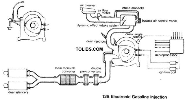
As schematic shows, 1986-87 RX-7 has dual outlets, not dual exhausts. Althoughit is a considerable improvement over previous stock systems because of increased capacity through the use of two mufflers, it is more restrictive than a header system.
EXHAUST SYSTEM
With a reciprocating engine, the standard approach to eliminating restrictions in the exhaust tract is to remove the original-equipment exhaust manifold/muffler assembly and replace it with a set of tubular headers and a free-flowing muffler. This technique is equally effective when applied to a rotary engine, but it becomes a bit more involved, especially with street-driven vehicles. When the rotor spins past the exhaust port, it signals an all-out assault of heat and noise; special measures are required to deal with the onslaught.
At full throttle, rotary exhaust-gas temperatures (EGT) are extremely high possibly reaching 1600 - 1800F. Compare this to an EGT of 1150-1400F for the typical reciprocating engine operating at wide open throttle. In order to withstand a rotary’s fiery breath, header tubing must be either extra heavy-wall mild steel or stainless steel. Stainless offers an attractive appearance, but it is expensive and difficult to weld. Consequently, mild steel is usually the material of choice with most manufacturers offering headers for Mazda 12A and 13B engines.