Mazda 929 Workshop Repair Manual All Models
PACEMAKER CUSTOMER REPAIR MANUAL MAZDA 929
This manual covers all mazda 929 models
Detailed description of removal, installation, adjustments, repair, overhaul and servicing of all the major vehicle parts, incl. engine, carburettor, valves, clutch, brakes, steering, transmission, electrical equipment with exploded views and complete technical data and wiring diagram
ISBN No. 0 907779 00-X
The Publisher would like to thank Mr. R. Pickering for producing many of the illustrations in this Repair Guide.
Our Thanks also to Mazda (UK) Ltd. for allowing Mr. P. Russek to attend their Service Training Courses.
No part of this publication may be reproduced, stored in a retrieval system or transmitted in any form, electronic, mechanical, photocopying, recording, translating or other means without prior written permission by the author.
No Liability can be accepted for any Inaccuracies or Omissions in this Repair Guide, although every possible care has been taken to make it as complete and accurate as possible. We have tried to cover all models produced at present, but are unable to refer to all modifications and changes for certain markets or up-dating of models.
PREFACE
Small though this Workshop Manual is in size, it lacks no detail in covering the whole of the servicing and repair of the Mazda 929 vehicles in Saloon, Coupe and Estate form, with manual or automatic transmission. Brief, easy to follow instructions are given, free from all unnecessary complication and repetition, yet containing all the required technical detail and information, and many diagrams and illustrations.
Compiled and illustrated by experts, this guide provides a concise source of helpful information, all of which has been cross-checked for accuracy to the manufacturer's official service and repair procedures. Where special tools are required these are referred to, and identified, in the text and we do not hesitate to advise you if we feel that the operation cannot be properly undertaken without the use of such tools. The author has attended two of the Mazda Service Training Courses (Training Certificate reproduced on Page 4) in order to include as much technical know-how as possible.
The reader's own judgement must ultimately decide just what work he will feel able to undertake but there is no doubt that, with this guide to assist him, there will be many more occasions where the delay, inconvenience and cost of garage repairs can be avoided or minimised.
This guide is produced in a handy glove-pocket size with the aim that it should always be kept in the vehicle whilst you are travelling. Many garage mechanics them selves use these publications in their work and if you have the book with you in the car you will have an invaluable source of reference which will quickly repay its modest initial cost. Always use genuine Mazda spare and replacement parts.
General Data Information
This Repair Guide covers the range of Mazda 929 models, being the piston engine version of the Mazda RX-4 Rotary Engine Vehicle. The engine of the Mazda 929 is a 1,769 c.c. (108 cu.in.) unit, with four cylinders and an overhead camshaft. The camshaft runs in bearings (shells) in the cylinder head. The crankshaft is supported in five bearings of the shell-type and drives the camshaft and the oil pump by means of chains. All models are fitted with a four- or five speed manual transmission or a Borg-Warner automatic transmission.
General Servicing Notes
The servicing and repair instructions in this Repair Guide are laid out in an easy-to-follow step-by-step order and no difficulties should be encountered if the text and diagrams are followed carefully and methodically. The author of this Repair Guide has attended a comprehensive Mazda Service Training Course and all operations have as far as possible been carried out without the use of special tools. Even if the number of a special service tool is given, we have tried to overcome this by giving alternative methods.
In order that space should be allocated to all possible technical data we do not repeat each time the more obvious and simple steps necessary to conform to good engineering practice. It may, -however, be useful to briefly draw your attention to the more important general procedures and to list some points of general interest.
Always use the torque wrench settings given in the various sections of the Repair Guide. Bolts and nuts must always be in a clean and dry condition (use sealer only where recommended). Threads and faces must be undamaged and free from burrs or scoring.
All joint washers, gaskets, tab and lock washers, split pins and "0" rings should be renewed on assembly. Oil seals will, in the majority of cases, also need renewal if the shaft has been removed from the seal lip.
Reference to left-hand and right-hand sides (usually shown as L.H. or R.H.) is always to be taken as when the vehicle is viewed from the rear, facing forward.
Adequate precautions must always be taken to ensure that the vehicle is properly supported at all times, particularly if work is to be carried out on the underneath of the car. When the vehicle is to be raised, always support on stands and do not rely on a jack on its own. Support at the front under the crossmembers at the rear, under the rear axle casing.
Dirt, grease and mineral oil will rapidly destroy the seals of any hydraulic system and even the smallest amounts must be avoided at all times. Use clean brake fluid of the recommended specification to clean the hydraulic system.
Many of the instructions in this Repair Guide will cover the steps to completely dismantle or assemble a unit but, obviously, in some cases this may not always be necessary or desirable.
Use only the recommended greases and oils on the vehicle. Your Owner's Handbook should be used to complement the basic specifications given in this Repair Guide and will indicate the various proprietory products recommended as suitable.
Engine - Removal and Installation
Removal and installation of any of the engines covered in this Repair Guide follows the same general procedures in each case, differing only in minor aspects, depending on the model and parts fitted. The engine is in each case removed without the gearbox if this is desired. A suitable hoist or crane is to be attached to the engine hangers to allow the unit to be lifted towards the front and upwards, out of the engine compartment. In every case the coolant must be drained and the battery disconnected and removed. The coolant taps are at the bottom of the radiator and on the side of the engine, on the side of the brake fluid reservoir. Support the vehicle on stands of adequate strength if necessary. Support only under the front suspension crossmembers, the rear axle casing or the side jacking points. Drain the engine oil.
Exploded view of the cylinder head
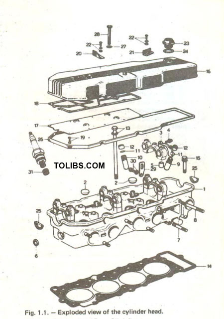
- Cylinder head
- Blind plug
- Thrust plate
- Bolt
- Dowel pin
- Blind plug
- Manifold stud
- Manifold stud
- Inlet valve guide
- Exhaust valve guide
- Retaining ring
- Valve guide seal
- Cylinder head bolt
- Cylinder head gasket
- Oil deflector
- Gasket
- Bolt
- Bracket
- Bracket
- Screw
- Oil filler cap
- Sealing washer
- Sealing insert
- Rocker cover gasket
- Sealing washer
- Bolt
- Lifting bracket
- Bolt
- Threaded insert
Jack up the vehicle and from underneath remove the clutch housing cover and the starter motor. Separate the exhaust pipe from the manifold connection. Support the gearbox on a suitable trolley jack and raise the engine until all load is taken off the engine mountings. Unscrew the nuts and bolts securing the gearbox to the engine. Attach a suitable lifting sling to the engine hanger brackets and a suitable hoist or other lifting device and take up all slack. Remove the right- and left-hand engine mounting brackets. Pull the engine forward until it is free from the clutch shaft and then lift the engine carefully from the engine compartment, taking care that all connections have been separated.
If the vehicle is fitted with Exhaust Emission Control Equipment, disconnect additionally all wires, pipes and leads between the engine and the equipment. Make sure that each connection is clearly marked before removing to facilitate re-connection.
Installation of the engine is carried out by following the instructions in reverse sequence to removal. Fill the engine with the specified lubricant and fill the coolant system. Run the engine and check for possible leaks in cooling, fuel and lubrication systems.
Engine - General Dismantling
Before commencing any dismantling of the engine, thoroughly clean all exterior surfaces to prevent any foreign matter finding its way into the engine cavities when the seal faces are separated.
If possible, mount the engine in a suitable stand. If such a stand is not available, make sure that the engine is well supported when placed on a workbench for dismantling.
First remove the ignition distributor. To do this, withdraw the spark plug cables from the plugs and the vacuum hose from the distributor. Undo the locknut for the distributor and withdraw the distributor. Disconnect the fuel hose from the pump outlet. Remove the bolt securing the pump to the cylinder block and liftoff the pump together with the intermediate flange and the gaskets. The pump will have to be tilted slightly towards the top to disengage the pump operating lever.
Undo the bolts securing the fan and the pulley from the water pump hub and remove fan and pulley. The water pump is fitted to the front timing cover and can now be unscrewed. Remove the alternator. Remove the water pump gasket.
Remove the screws securing the thermostat housing to the cylinder head and lift off the housing together with its gasket. Withdraw the thermostat. Unscrew the engine hanger bracket and remove the inlet manifold from the cylinder head and lift off together with the carburettor and the manifold gasket. Unscrew the oil filter and the oil pressure switch. Special tool 49 0223 195 is available for the removal of the oil filter. If this tool is not at hand, the oil filter can be removed with a clamp wrench. Most accessory shops sell now universal oil filter clamp wrenches, so that this problem is easily overcome.
Remove the camshaft and the cylinder head as follows:
Unscrew the rocker cover bolts and lift off the cover together with the gasket. There are two semi-circular oil seals, one at each side of the cylinder head which must be removed. Insert a strong screwdriver into the teeth of the flywheel ring gear and remove the nut securing the distributor drive gear to the end of the camshaft. Slide the drive gear off the camshaft and using a large open ended spanner, remove the nut securing the camshaft sprocket (see Fig. 1.2.). Unscrew the cylinder head bolts in the reverse order to the sequence shown in Fig. 1.3.
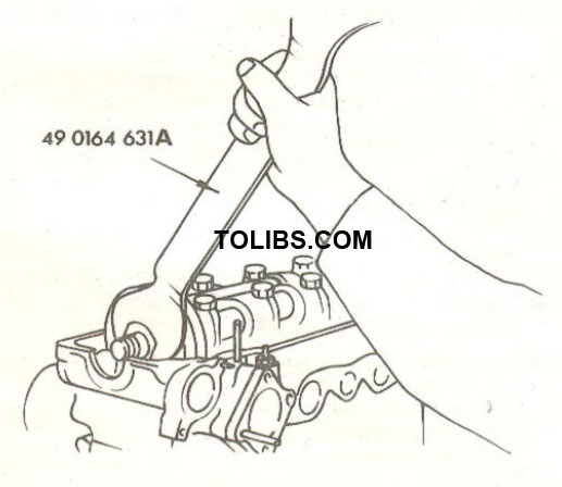
Fig. 1.2. - Removal of the locknut for the camshaft sprocket. The distributor drive gear has already been removed from the end of the camshaft.
Fig. 1.3. - Tightening sequence for the cylinder head bolts. The bolts are slackened in reverse ardor starting at "10".
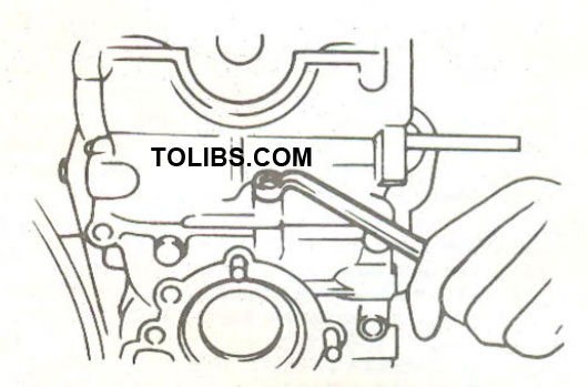
Fig. 1.4. - When removing the cylinder head, note that a bolt is situated on the outside between cylinder head and timing cover.
An additional bolt is located on the outside of the cylinder head, between cylinder head and timing cover (see Fig. 1.4.), which must also be removed. Make sure that the cylinder head bolts are loosened gradually and evenly in several stages.
Lift off both rocker shafts. The rocker pedestals are located on hollow dowels and a screwdriver may be necessary to lift them off. Withdraw the camshaft to wards the rear, at the same time disengaging the camshaft sprocket from the shaft. Take care not to damage the bearing shells in the cylinder head. Lift out the shells and keep them together with the other set in the rocker pedestals. The camshaft sprocket can either be left in the chain (it will not drop into the timing chamber) or can be removed from the chain. In this case, tie up the chain in a suitable manner, especially if it is not intended to carry out further dismantling work.
NOTE: When only the camshaft or the cylinder head is removed,puil the timing chain upwards after removing the camshaft sprocket to prevent the slipper head of the chain tensioner from disengaging and thereby making it difficult to adjust the timing.
Engine - General Re-Assembly
This section covers general re-assembly procedures and further detailed information on servicing and overhaul is given in the sections commencing at 1.4. For all engines, the general instructions below should be followed at all times.
Take care to keep all parts in as clean a condition as possible. Benches, tools and rugs should be kept free of swarf, dirt and all other foreign matter. When installing any part that rotates or slides be sure to apply a film of clean engine oil. Do this BEFORE the parts are assembled and not afterwards.
Use new gaskets and renew all split pins, lock washers and plates and damaged bolts and nuts. Inspect all oil seals and replace if the sealing lip shows the slightest damage or deterioration.
Follow all specific tightening torque values which are given in Section 1.5. and at the end of other sections clutch, gearbox, etc. It is most important to note that some tightening torque values are different for certain engines and these values must always be followed.
With all parts serviced and overhauled as necessary, the assembly sequence should be as follows:
Take the assembled pistons and connecting rods (see Section 1.4.3.) and lay them out in their cylinder order. Make sure that the "F" in the piston pin boss and the oil hole in the connecting rod are relative to each other as described in Section 1.4.3..With the engine resting on the cylinder block face, fit the crankshaft and parts. Fit the oil seal into the rear end of the cylinder block. Fit the side seals as described in Section 1.4.4.
Place the upper half of the crankshaft main bearing shells into the block. Install, the upper halves of the thrust washers, making sure that the oil grooves are facing the thrust faces. Lift the crankshaft into position and fit the remaining bearing shells, the thrust washers and the bearing caps.
The bearing caps are marked with a number (1 to 5) and their identification can be taken from Fig. 1.6. Make sure that the main bearing caps are installed in their original positions.
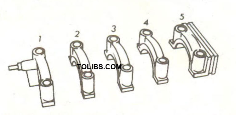
Fig. 1.6. The identification of the main bearing caps. Arrows in the centre caps (except No. 1 and No. 5) indicate which side of the caps must face towards the front of the engine.
Fit the main bearing cap bolts and tighten them to 8.4 - 9.0 kgm (61 - 65 Ib.ft.).
Tighten the cap bolts in the following sequence: Centre bearing, then the cap in front of the centre, then that behind the centre bearing, then the front and finally the rear cap. Finally check the crankshaft end float.
Oil the pistons and connecting rods and use a ring compressor to insert the assemblies into the top of the block. The piston front mark "F" must face the front of the engine. Ring gaps must be arranged as described in Section 1.4.3.1. Fit the connecting rod bearing caps io their proper positions, making sure that the identification numbers stamped near the fitting surfaces with the caps are properly matched. Tighten the cap bolts to 5.0 - 5.5 kgm (36 - 40 Ib.ft.) in several stages in the order given above.