Mazda Engine Workshop Manual
Mazda Engine Workshop Manual B6-DOHC, BP-DOHC
Servicing a vehicle can be dangerous. If you have not received service-related training, the risks of injury and property damage increase. The recommended servicing procedures for the vehicle in this workshop manual were developed with Mazdatrained technicians in mind. This manual may be useful to non Mazda trained technicians, but a technician with our service related training andexperience will be at less risk when performing servicing operations. However, all users of this manual are expected to know general safety procedures.
This manual contains “Warnings” and “Cautions” applicable to risks not normally encountered in a general technician’s experience. They should be followed to reduce the risk of injury and the risk that improper service or repair may damage the vehicle or render it unsafe. It is also important to understand that the “Warnings” and “Cautions” are not exhaustive. It is impossible to warn of all the hazardous consequences that might result from failure to follow the procedures.
The procedures recommended and described in this manual are effective methods of performing service and repair. Some require tools specifically designed for a specific purpose. Non recommended procedures and tools should include consideration for safety of the technician and continued safe operation of the vehicle.
Parts should be replaced with genuine Mazda replacement parts, not parts of lesser quality. Use of a nonrecommended replacement part should include consideration for safety of the technician and continued safe operation of the vehicle.
This manual explains the disassembly, inspection, repair, and reassembly procedures for the above-indicated engine. In order to do these procedures safely, quickly, and correctly, you must first read this manual and any other relevant service materials carefully.
The information in this manual is current up to June, 1994. Any changes that occur after that time will not be reflected in this particular manual. Therefore, the contents of this manual may not exactly match the mechanism that you are currently servicing.
Conversion to SI Units (Systeme International d’Unites)
All numerical valuesin this manual are based on SI units.Numbers shownin conventional units are converted from these values.
Rounding off
Converted values are rounded off to the same number of places are the SI unit value. For example, if the SI unit value is 17.2 and the value after conversion is 37.84, the converted value will be rounded off to 37.8.
Upper and lower limits
When the data indicates upper and lower limits, the converted values are rounded down if the SI unit value is an upper limit and rounded up if the SI unit value is a lower limit. Therefore, converted values for the same SI unit value may differ after conversion. For example, consider 2.7 kgf/cm2 in the following specifications:
- 210-260 kPa { 2.1-2.7 kgf/cm2 , 30-38 psi }
- 270-310 kPa { 2.7-3.2 kgf/cm2 , 39-45 psi }
The actual converted values for 2.7 kgf/cm2 are 264 kPa and 38.4 psi. In the top specification, 2.7 is used as an upper limit, so its converted values are rounded down to 260 and 38. In the bottom specification, 2.7 is used as a lower limit, so its converted values are rounded up to 270 and 39.
ENGINE STAND MOUNTING/DISMOUNTING
MOUNTING
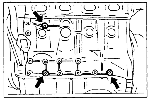
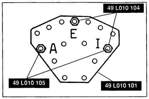
Use the holes shown in the figure.
Install the SST (arms) to the holes as shown in the figure, and hand tighten the SST (bolts).
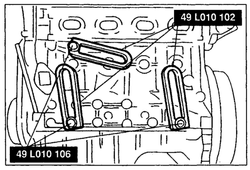
Assemble the SST (bolts, nuts, and plate) in the specified positions marked A, E, and I.
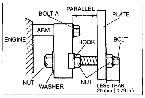
Install the SST assembled in step 3 to the respective arms. Adjust the SST (bolts) so that less than 20 mm { 0.79 in} of thread is exposed. Make the SST (plate and arms) parallel by adjusting the SST (bolts and nuts). Tighten the SST (bolts and nuts) to affix the SST firmly.
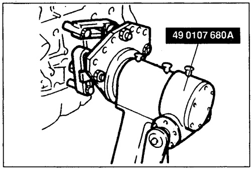
Mount the engine on the SST (engine stand).
DISMOUNTING
Dismount in the reverse order of mounting.