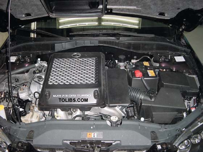
NC Miata MX-5 MZR Engine Timing Procedure
Mazda NC Timing Manual
Technical TrainingJob AidEngine Timing: LF 2.0L, L3/L3T 2.3L
Models
- 2001-present B2300 B-Series Truck (L3 2.3L)
- 2003-present MAZDA6 (L3 2.3L)
- 2004-present MAZDA3 (LF 2.0L / L3 2.3L)
- 2005-present Tribute (L3 2.3L)
- 2006-present MAZDASPEED6 (L3T 2.3L DISI Turbo)
- 2006-present MX-5 Miata (LF 2.0L)
- 2007-present CX-7 (L3T 2.3L DISI Turbo)
- 2007-present MAZDASPEED3 (L3T 2.3L DISI Turbo)
Description
Vehicles with any of the following symptoms may have slipped timing:
- DTC P0340
- Lack of power
- No start/engine seized.
The LF and L3 engines are interference engines. If the timing slips the valves may contact the pistons. Verify base camshaft/crankshaft timing and correct if necessary. If the engine runs rough after correcting cam timing, perform a compression test. If compression is low, perform a cylinder leakdown test and determine leakage. Replace the cylinder head if necessary.
Follow specific procedures to time LF 2.0L and L3/L3T 2.3L engines. Timing the LF / 2.0L engine, the L3 and L3T / 2.3L engines must be done following specific procedures. This Job Aid explains how to verify base engine timing (relation of intake camshaft, exhaust camshaft,crankshaft sprocket and crankshaft pulley) and how to correct timing if it is incorrect. Do not skip any steps and always begin by Inspecting Engine Timing on page 3.
NOTE: The camshaft, crankshaft, crankshaft sprockets and crankshaft pulley are friction-fit components. Loosening any of these components requires re-timing the camshafts or crankshaft. Failure to properly re-time the engine will result in severe engine damage.
Technical Training
Inspecting Engine Timing
- Remove the lower engine splash shield.
- MAZDA3, MAZDA6, MAZDASPEED6 and Tribute: remove the passenger side splashshields, plastic fender skirts, and the passenger axle shaft to access the crankshaft pulleybolt and the engines blind plug bolt.
- CX-7 MAZDASPEED3, MAZDSPEED6: relieve fuel pressure from the high pressure fuelsystem (the high pressure fuel pump must be removed to use the camshaft alignment plate).
- Ignition OFF
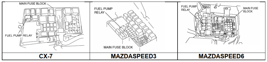
- Disconnect the Fuel Pump Speed Control Relay (labeled CIRCUIT in the underhoodfuse box).
- Remove the fuel filler cap.
- Crank the engine until the vehicle stalls.
- Crank the engine several more times.
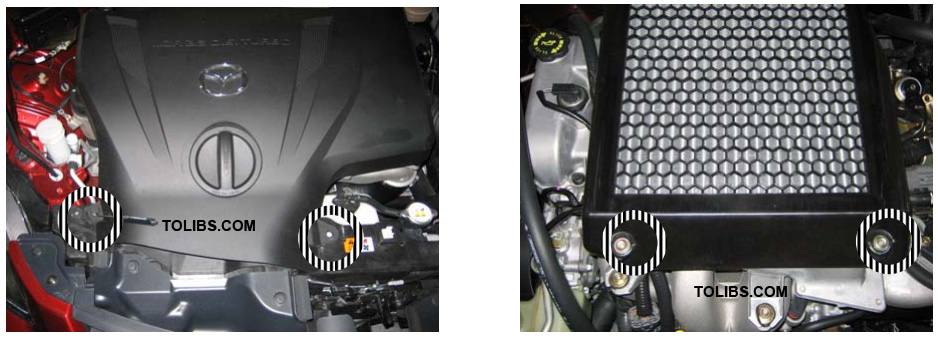
- CX-7 MAZDASPEED3, MAZDSPEED6: remove the intercooler shroud and the intercooler to access the spark plugs.
- A. MAZDASPEED3 and MAZDASPEED6: remove the 10mm bolts securing the plastic intercooler cover.
- A. CX-7: remove the two plastic clips securing the intercooler shroud to the vehicle and remove the three 10mm bolts securing the plastic intercooler cover.
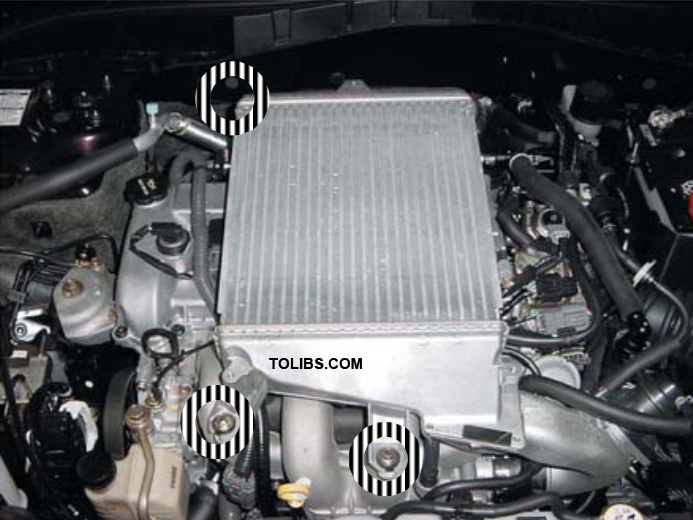
- B. Remove the three 12 mm bolts securing the intercooler to the intake.
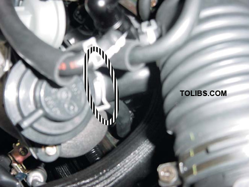
- C. Remove the air bypass control hose clamp and disconnect the hose from the valve.

- D. Loosen the bypass outlet hose clamp.
- E. Loosen the hose clamp from the turbo outlet to the intercooler inlet (10mm or #2 Phillips). NOTE: Mark the position of the hose clamp by placing a mark on the hose and on the intercooler to make assembly easier.
- F. Loosen the hose clamp at the intercooler outlet where it connects to the intake manifold(10mm or #2 Phillips).
- G. Separate the intercooler from the boot at the turbo outlet, separate the intercooler fromthe boot at the intake manifold, and separate the air bypass hose outlet. Remove theintercooler from the vehicle.
- A. MAZDASPEED3 and MAZDASPEED6: remove the 10mm bolts securing the plastic intercooler cover.
- MX-5 Miata: remove the fresh air box and the battery to access the front of the engine.
- Disconnect the negative battery cable., separate the intercooler fromthe boot at the intake manifold, and separate the air bypass hose outlet. Remove theintercooler from the vehicle
- Remove the accessory drive belt by turning the tension bolt (14mm) clockwise.
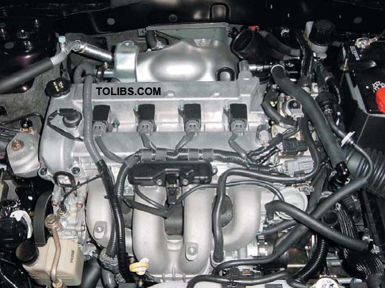
- Remove the ignition coil(s) (four 8mm).
- Blow compressed air in the park plug holes to remove dirt and debris.
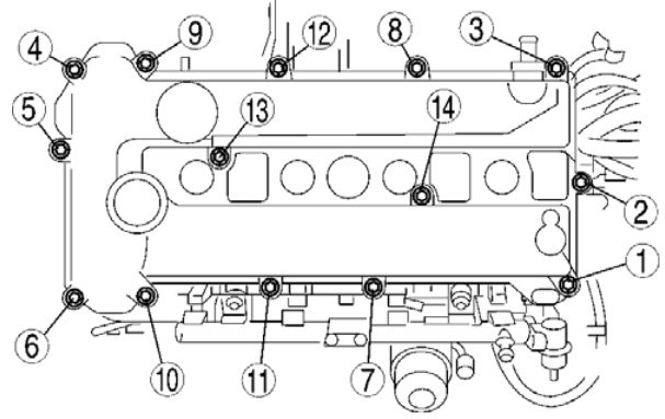
- Remove the valve cover (8mm).
- Remove all spark plugs to make the engine easier to turn over.
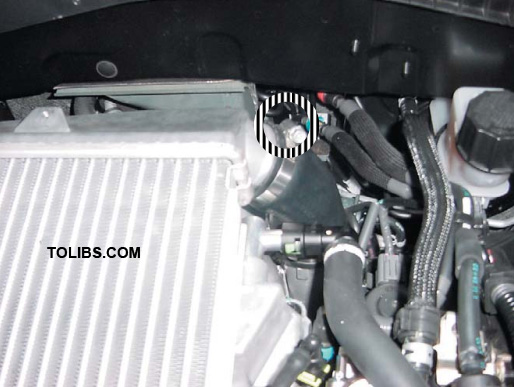
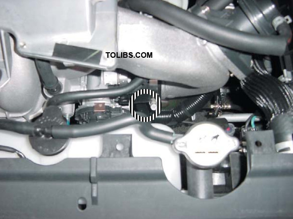
- Remove the blind plug bolt behind the CKP sensor (13mm).
- Install the crankshaft timing peg SST 303-507. NOTE: Installing the SST timing peg in this step will prevent the engine from being rotated in the clockwise direction.
- Using the crankshaft pulley bolt (21mm), turn the crankshaft clockwise until it stops turning.The crankshaft stops when the #1 cylinder counterweight contacts the timing peg.
- For vehicles with Variable Valve Timing (VVT) including MAZDA3 L3, MX-5 Miata,MAZDA6 L3, MAZDASPEED3, MAZDASPEED6,and Tribute L3: the VVT mechanismnormally locks when the engine shuts off. Make sure the VVT camshaft gear is lockedbefore attempting to adjust timing. The notches in the gear must be aligned so the timing isfixed. If it is not, turn the camshaft to lock the gear.
- Place an M6 bolt (6mm X18mm) through the crankshaft pulley into the timing cover. Canyou install the bolt and does it fit flush through the timing bolt cover?
- Yes, the crankshaft pulley is properly timed. Note this on the Repair Order andGo tostep 17.
- No, the crankshaft pulley is out of time. Note this on the Repair Order and Goto step#17.
- Attempt to place the camshaft alignment plate SST into the slots on the rear of thecamshafts. Does the SST fit?
- Yes, the camshaft alignment plate fits. The camshafts are properly timed. Note this onthe Repair Order.Go to step 18.
- No, the camshaft alignment plate does not fit. One or both camshafts are out of time.Note this on the Repair Order.Go to step 18.
- Review the notes you made on the repair order and determine which repair procedure to perform.