Mazda Ranger Drifter Repair Workshop Manual

MAZDA/FORD RANGER DRIFTER ENGINE CHASSIS and BODY Repair Manual
This Manual has been prepared to provide information covering normal service repairs and maintenance for the RANGER / DRIFTER SERIES. This manual contains the procedures for performing all of the required service operations. The procedures are divided into the following five basic operations.
- Removal/Installation
- Disassembly/Assembly
- Replacement
- Inspection
- Adjustment
Simple operations which can be performed easily just by looking at the vehicle, such as removal/installation of parts, jacking, vehicle lift, cleaning of parts, and visual inspection, have been omitted. The procedures for inspections and adjustments are divided into steps. Important points in regard to the location and contents of the procedures are explained in detail and are shown in the illustrations.
MAZDA RANGER DRIFTER OVERHAUL MANUAL F161-20-99A
VEHICLE IDENTIFICATION NUMBERS (VIN)
U.K. specs.
WF0 DMB]30WW 100001
WF0 LMB]30WW 100001
WF0 DMDD30WW 100001
WF0 LMDD30WW 100001
WF0 DMFE40WW 100001
WF0 LMFE40WW 100001
European specs.
WF0 BMF]30WW 100001
WF0 BME]30WW 100001
WF0 DMF]30WW 100001
WF0 DME]30WW 100001
WF0 LMF]30WW 100001
WF0 LME]30WW 100001
WF0 BMD]30WW 100001
WF0 BMC]30WW 100001
WF0 DMD]30WW 100001
WF0 DMC]30WW 100001
WF0 LMD]30WW 100001
WF0 LMC]30WW 100001
WF0 BMB]30WW 100001
WF0 BMA]30WW 100001
WF0 DMB]30WW 100001
WF0 DMA]30WW 100001
WF0 LMB]30WW 100001
WF0 LMA]30WW 100001
WF0 BMFE40WW 100001
WF0 BMEE40WW 100001
WF0 DMFE40WW 100001
WF0 DMEE40WW 100001
WF0 LMFE40WW 100001
WF0 LMEE40WW 100001
WF0 BMD]40WW 100001
WF0 BMC]40WW 100001
WF0 DMD]40WW 100001
WF0 DMC]40WW 100001
WF0 LMD]40WW 100001
WF0 LMC]40WW 100001
WF0 BMB]40WW 100001
WF0 BMA]40WW 100001
WF0 DMB]40WW 100001
WF0 DMA]40WW 100001
WF0 LMB]40WW 100001
WF0 LMA]40WW 100001
General specs. (L.H.D.)
MNC BSF]30WW 100001
MNC BSE]30WW 100001
MNC BSF]3WWW 100001
MNC BSE]3WWW 100001
MNC BSB]30WW 100001
MNC BSA]30WW 100001
MNC BSB]3WWW 100001
MNC BSA]3WWW 100001
General specs. (R.H.D.)
MNB BSF]30WW 100001
MNB BSE]30WW 100001
MNB BSBD50WW 100001
MNB BSAD50WW 100001
MNB BSB]30WW 100001
MNB BSA]30WW 100001
Repair procedure

- Most repair operations begin with an overview illustration. It identifies the components, shows how the parts fit together, and describes visual part inspection. However, only the removal/installation procedures which need to be performed methodically have written instructions.
- Expendable parts, tightening torques, and symbols for oil, grease, and sealant are shown in the overview illustration. In addition, symbols indicating parts which require the use of special service tools for removal/installation are also shown.
- The procedures are numbered and the part that is the main point of that procedure is shown in the illustration with the corresponding number. Occasionally, there are important points or information concerning a procedure. Refer to this information when servicing the related part.
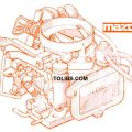
ENGINE DISASSEMBLY/ASSEMBLY
TIMING BELT DISASSEMBLY/ASSEMBLY
- Disassemble in the order shown in the figure.
- Assemble in the reverse order of disassembly

| 1 | Water pump |
| 2 | Vacuum pump |
| 3 | Cylinder head cover + Assembly Note |
| 4 | Timing belt cover + Assembly Note |
| 5 | Tensioner, Tensioner spring + Disassembly Note |
| 6 | Pulley plate |
| 7 | Timing belt + Disassembly Note + Assembly Note |
Tensioner, Tensioner Spring Disassembly Note
Turn the crankshaft clockwise and align the timing marks as shown.

Remove the tensioner and tensioner spring.
Timing Belt Disassembly Note
Caution: The following will damage the belt and shorten its life; Forcefully twisting it, turning it inside out, or allowing oil or grease on it.
Mark the timing belt rotation on the belt for proper reinstallation.

- Turn the crankshaft clockwise and align the timing marks as shown.
- Verify that the FIP attaching bolts and nuts are tightened to the specified torque. This must be done to prevent overtensioning of the timing belt after it has been installed.
- Install the timing belt.
- Install the tensioner, tensioner spring, and the lock bolt.
- Turn the crankshaft clockwise twice, and align the timing marks. If they are not aligned, remove the timing belt and repeat from Timing Belt Assembly Note step 1.
- Loosen the tensioner lock bolt to apply tension to the belt. Do not apply tension other than that of the tensioner spring.
- Tighten the tensioner lock bolt. Be sure the tensioner does not move together with the bolt rotation.
- Turn the crankshaft clockwise twice, and check the timing belt deflection as shown. If it is incorrect, repeat from Tensioner, Tensioner Spring Disassembly Note.
Cylinder Head Cover Assembly Note
Before installing the cylinder head cover, inspect the valve clearance.
(Refer to ENGINE INSPECTION/REPAIR, VALVE CLEARANCE INSPECTION.)
Apply silicone sealant to the cylinder head as shown.
Thickness 1.5-2.5 mm {0.060-0.098 in}

Tighten cylinder head cover bolts A and B.
Tightening torque
1.5-2.9 N·m {15-30 kgf·cm, 14-26 in·lbf}

Tighten the cylinder head cover bolts in the order shown.
Tightening torque
5.0-8.8 N·m {50-90 kgf·cm, 44-78 in·lbf}
Mazda RANGER DRIFTER REPAIR MANUAL F161-10-99A
VEHICLE IDENTIFICATION NUMBERS:
U.K. specs.
JMZ UN1B320W 100001
JMZ UN8B320W 100001
JMZ UN8F420W 100001
European specs.
JMZ UN1*620W 100001
JMZ UN1*62WW 100001
JMZ UN1*320W 100001
JMZ UN1*32WW 100001
JMZ UN8*720W 100001
JMZ UN8*72WW 100001
JMZ UN8*320W 100001
JMZ UN8*32WW 100001
General specs. (L.H.D.)
MM7 UNY02100 100001
MM7 UNY021WW 100001
MM7 UNYOW100 100001
MM7 UN2*6*00 100001
MM7 UN2*6*WW 100001
MM7 UN3*6*00 100001
MM7 UN3*6*WW 100001
MM7 UN2*2*00 100001
MM7 UN2*2*WW 100001
General specs. (R.H.D.)
MM6 UNY02100 100001
MM6 UNYOW100 100001
RELATED MATERIALS
- B Series Training Manual ..3333-10-99A
- Engine Workshop Manual WL, WL Turbo ..1532-10-96C
- Engine Workshop Manual G6 ..1640-10-99A
- Engine Workshop Manual F2 ..1641-10-99A
- Manual Transmission Workshop Manual
- M15M-D M15MX-D ..1645-10-99A
- Manual Transmission Workshop Manual
- R15M-D R15MX-D..1642-10-99A
- B Series Wiring Diagrams
- (European, General specs. (L.H.D.)) ..5449-10-99A
- B Series Wiring Diagrams
- (European, General specs. (R.H.D.)) ..5450-10-99A
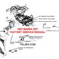
ENGINE REMOVAL/INSTALLATION
Warning
- Fuel vapor is hazardous. It can very easily ignite, causing serious injury and damage. Always keep sparks and flames away from fuel.
- Fuel line spills and leaks are dangerous. Fuel can ignite and cause serious injuries or death and damage. Fuel can also irritate skin and eyes. To prevent this, always complete the "Fuel Line Safety Procedure" in section F3, F4. (Refer to section F3-F4, FUEL SYSTEM, BEFORE REPAIR PROCEDURE.)
- Disconnect the negative battery cable.
- Drain the engine coolant. (Refer to Section E, COOLING SYSTEM SERVICE WARNINGS.) (Refer to Section E, ENGINE COOLANT, ENGINE COOLANT REPLACEMENT.)
- Remove the air cleaner and air hose (F2, CIS).
- Remove the front pipe.
- Disconnect the accelerator cable, bracket (F2 CIS), heater hoses, high-tension leads, and vacuum hoses.
- Remove the radiator. (Refer to Section E, RADIATOR, RADIATOR REMOVAL/INSTALLATION.)
- Remove the cooling fan and cooling fan pulley.
- Remove the drive belt. (Refer to DRIVE BELT, DRIVE BELT ADJUSTMENT.)
- Disconnect the fuel hoses. (Refer to Section F3-F4, FUEL SYSTEM, BEFORE REPAIR PROCEDURE.) (Refer to Section F3-F4, FUEL SYSTEM, AFTER REPAIR PROCEDURE.)
- Remove the transmission. (Refer to Section J1-J2, MANUAL TRANSMISSION, MANUAL TRANSMISSION REMOVAL/INSTALLATION.)
- Remove the P/S oil pump with the oil hose still connected. Position the P/S oil pump so that it is out of the way. (Refer to Section N, ENGINE SPEED SENSING POWER STEERING, POWER STEERING OIL PUMP REMOVAL/INSTALLATION.)
- Remove the A/C compressor with the pipe still connected. Position the A/C compressor so that it is out of the way.
- Remove in the order indicated in the table.
- Install in the reverse order of removal.
- Start the engine and: (1) Inspect the engine oil, engine coolant, transmission oil, and fuel leakage. (2) Inspect the ignition timing, idle speed and idle mixture. (Refer to Section F3-F4, ENGINE TUNE-UP.)
- Perform a road test.