Nissan Cabstar Ascendant A18 13TJ Operator Manual
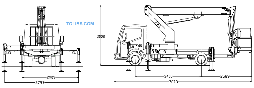
TECHNICAL SPECIFICATION ASCENDANT A18-13TJ TRUCK MOUNT
GENERAL
This is our multi-purpose 18m maximum working height access platform mounted onto a RENAULT MAXICITY/ NISSAN CABSTAR of 3,500kg GVW and 3400mm wheel-base. The telescopic boom plus fly arrangement gives excellent controllability when manoeuvring. The multiple jacking configurations ensure the machine can be set up for working in the most confined spaces.
The design concept includes for oversized structural elements coupled to sensitive, electrohydraulic proportional controls ,making the machine feel safer and simpler than its contemporaries when being operated whilst requiring the minimum of maintenance. The unit is generally as shown on our attached drawings but specifically as described below:
PERFORMANCE
- SWL: 230kg
- Max working height: 18m
- Max platform height: 16m
- Max. working outreach: 13m
- Cage dimensions: 0.73m x 1.4m x 1.1m high
- Cage rotate: 160 deg.
- Closed height: 3.0m
- Closed width: 2.3m
- Travelling length: 7.0m
- Weight of unit: 3330kg including vehicle
CAGE
Formed from structural quality aluminium tubes the top rail is set back from the front of the cage providing finger protection and also presenting a flush face for the cage easing the problems associated with carrying large, flat objects e.g. overhead signs. Having an uninterrupted plan area of 0.73m x 1.4m the assembly is suitable for 2 men and tools for working. The cage features a 150mm high kickboard and a mesh floor. 160 degrees powered rotation fitted as standard.
BOOMS
A three stage telescopic main boom coupled to an independent fly boom forms the general concept of this particular unit. The main boom is driven in and out via a single telescope cylinder and system of wire ropes. The fly boom is 2.0m long and has an operating arc of 125 deg. Cage leveling is effected via a closed loop master/slave hydraulic cylinder arrangement complete with a manual trimming valve. The boom sections are formed from prefabricated folded sections seam welded together to produce a 6 sided box.
TURRET
Two substantial prefabricated box sections form the upright portion of this assembly giving the platform substantial lateral rigidity. An oversized pin sits between the booms and the turret. A large slewing ring, driven by a hydraulic planetary gearbox and pinion connects this unit to the chassis.
CHASSIS
Formed into a box from deep folded channels, this unit features high torsional resistance combined with lightweight. Powered horizontal and vertical jacks are incorporated along with a none-slip deck. An “A” frame mounted behind the cage provides a stowing point for the booms during transport. Steps are provided for easy access to the vehicle deck. Legally proportioned side guards are included between the vehicle’s wheels.
CONTROLS
The machine is fitted with H-type jacks that are controlled from the lower floor position. The jacks are fail-safe in principle preventing the platform from operating unless all 4 are in firm contact with the supporting surface. Cage controls of the electro hydraulic proportional type, duplicated at the base, give very smooth control of the platform throughout its operating range. The platform will automatically default to the appropriate working envelope as the jacks are deployed. All limiting devices are positively failsafe in operation. Engine start/stop is provided at each operating location.
EMERGENCY CONTROLS
A manually operated hand pump is included to return the platform to the transport position.
OUTRIGGERS
Three outrigger configurations are provided on this machine:
- Full width – allows maximum working load at full outreach through 360-deg. rotation. Jack spread 3.8m.
- One sided – allows maximum working load at full outreach through180 deg rotation on fully jacked side. Jack spread 2.9m.
- Narrow Jacking - allows maximum working load at limited outreach through 360 degrees. Jack spread 2.35m.
INTERLOCKS
- Booms cannot be raised until jacks are correctly deployed.
- Jacks cannot be operated unless booms are in transport position.
- PTO cannot be engaged unless handbrake is on.
- If engine is running starter cannot be engaged from the platform.
- The platform is automatically prevented from lowering or rotating into the cab or jacks.
- The platform will stop working should the cage be overloaded.
In addition to the above, warning lights are provided indicating:
- Booms not stowed.
- Jacks not stowed.
- One sided, narrow or full width jacking selected.
HYDRAULICS
The hydraulic system is of failsafe design throughout, with direct mounted load control valves fitted to all cylinders as a precaution against hose failure. The hydraulic power take off on the vehicle draws from a large capacity hydraulic oil tank. Filters are provided for suction, pressure and return lines. Pressure limiting valves are provided where appropriate.
SAFETY
The machine is designed in accordance with the requirements of the European machinery directive and will be provided with a “CE” mark. Testing of the unit will include a 125% overload test with the machine set up in its most unfavorable condition and a witness certificate provided.
STEELWORK PROTECTION
All steelwork will be shot-blasted prior to painting primer/undercoat and gloss finish. Typical paint thickness 90 to 110 microns.
PINS, BUSHES AND FITTINGS
All pins are stainless steel running in bushes that can be greased. All fittings, nuts and bolts are plated against corrosion.
A18-13TJ GENERAL ARRANGEMENT
TO ALL PERSONNEL:
Before the machine is unloaded from the transportation and unpacked, and before it is released into service, ASCENDANT ACCESS LTD recommend that this safety section should be read and fully understood by all individuals involved.
2.1 GENERAL SAFETY COMMENTS
NOISE: During normal operation the maximum sound level will not exceed 85 Dba.
THE OPERATOR
- Must be medically fit and have good eyesight and hearing. Any medical condition that may affect the safe use of this access platform must be reported e.g. epilepsy heart disease etc.
- Must have a good head for heights.
- Must have been trained in the safe use of access platforms, hold a current certificate and be fully conversant with the content of this manual.
- Must be very aware of the safety requirements concerning the persons working with them and the persons in the general vicinity of the access platform.
- Must not use this piece of equipment for any purpose other than that for which it was intended.
- Must carry out the necessary pre-start checks as described in the operating section of this manual and must not operate the platform should it not be in first class condition.
- Must never get on or off the work platform when elevated
2.2 WARNINGS
DO NOT operate this platform:
- On surfaces that are sloping, not hard standing or slippery without adequately supporting the platform. The 18-13 has been designed to work on surfaces with a minimum bearing strength of 50N/cm^2
- With items likely to increase the wind loading on the platform above acceptable levels e.g. notice boards etc.
- With any equipment in the cage likely to increase the working height or outreach e.g. ladders.
- For any special purpose that may produce special loads or forces. (as use of a crane). Any such application must be discussed with the manufacturer and their approval given.
- Near or close to live electrical conductors. The minimum safe distance for the 18-13 is 26.7m measured from the centre of rotation of the platform to the power lines. It is the operator’s responsibility to ensure this safe distance is maintained.
- Should it be necessary to work closer to the power lines then the operator must ensure that the power has been switched off before attempting to work, a written permit to work must be obtained from owners of the power cables or the responsible Persons.
- Unless there is a current certificate of safe use of the platform issued by a competent person.
- Into the path of oncoming traffic when working on a public highway.
2.3 MAXIMUM WIND SPEED
BEAUFORT WIND SPEED SCALE
The Beaufort wind speed scale is accepted internationally and is used in communicating weather conditions. It consists of numbers 1 to 17 each representing a certain velocity of wind at 10m above the ground in open conditions.
3.2 PRE-START CHECKS
The following pre-start checks must be carried out before operating the platform.
- Hydraulic fluid The oil level in the tank must be full when the platform is in the transport position.
- Cut out switches All cut-out and safety switches must be working correctly.
- Emergency stops Check that the emergency stops are operating correctly and that they are all in the run condition.
- Damaged/loose fittings Inspect the machine to ensure there are no signs of damage or loose hoses and fittings.
- Vehicle Check that there is enough fuel in the vehicle for a full shifts work.
3.3 SETTING UP
Do not attempt to set up the machine on steep slopes, ramps or soft ground. Maximum chassis inclination 0deg. Maximum slope machine may be levelled on, with provided spreader boards, is 3deg fore and aft (cab may be uphill or downhill.
- Park the vehicle in an appropriate location, remove from gear and apply the handbrake.
- Ensure that the working area of the platform is coned off.
- Depress the clutch and switch on the PTO/Platform Power switch (located on the dashboard). Release the clutch.
- Leave the vehicle cab and go to the outrigger control station positioned at the rear of the vehicle.
- Select, full width, near-side or off-side working by actuating the appropriate outrigger beam configuration. (Note; The outrigger display shows a green light to indicate which mode the outriggers are in.)
- Operate the outrigger jack controls until all four feet are just touching the ground, then, simultaneously operate the front (cab end) jacks and then the rear until all jacks are in firm contact with the supporting surface, the chassis is level (according to the level gauge) and the wheels are approximately 5-10cm off the ground. (Four green “Outriggers under load” lights should show on the outrigger control box).
- Check that the feet are in firm contact with the ground
EMERGENCY CONTROLS
- Red emergency stop buttons are located on the platform in the cage and at the base to stop the platform in an emergency.
- Emergency lowering of the booms is activated by depressing both the emergency power pack button and the deadman button simultaneously. This then allows normal operation of all functions through the emergency power pack.
- An emergency hand pump is provided (mounted on the near side of the chassis below the decking.) should all power fail. It is possible to operate the boom, telescope and fly boom to enable emergency lowering of the boom. To do this, manual operation of the appropriate hydraulic valve and main dump valve is needed. The ends of the hydraulic solenoid valves contain a rubber switch. Depress the appropriate solenoid valve and the main dump valve and then operate the emergency pump simultaneously to achieve movement.
STOWING
- Telescope the boom fully in and line it up with the docking pocket. Lower both main and fly booms fully ensure the cage rotate is in its central position. Leave the cage.
- Fully raise the outrigger jacks. (note this will not be possible if the booms are not stowed).
- Fully retract the outrigger beams. (Note this will not be possible unless all outrigger jacks are fully up). The green “outrigger stowed” should show on the outrigger control box.
- Check that the “booms not stowed” and “outriggers not stowed” lights are out on the vehicle dash.
- Disengage the PTO
- Switch off the platform.
- The vehicle is ready to drive away.
MAINTENANCE
Before the PLATFORM is accessed for maintenance purposes, the operator should be informed of the intended action and suitable warning signs erected. General tidiness should be considered a priority. Fluid spillage and debris should be cleaned up immediately to minimise the risk of slip, trip and / or fall. If the Platform is kept clean, it will make it easier to detect and rectify any faults that may occur. For the long-term, efficient operation of this Platform to be a practical possibility, it is suggested that a planned maintenance scheme is adopted. Check the Nissan Cabstar Schematic Diagrams Manual.
MAINTENANCE AND LUBRICATION SCHEDULE
The following page shows the recommended service schedule for the Ascendant 18-13TJ work platform. Explanation notes, where appropriate (marked thus*) follow the schedule. These notes must be read and understood. Ascendant Access recommends that this inspection/ service work be carried out by competent personnel.
GENERAL MAINTENANCE
Daily Checks
- Hydraulic fluid. Top up the fluid level with the machine in the transport condition and on level ground. Use SHF 22 (ISO) or equivalent.
- Safety checks on platform control circuit (see below)
- Outreach limiting device. (if fitted)
Weekly checks
- Apply grease to slew bearing and all grease nipples.
- Check boom pins/tie rods etc for damage.
- Check limit switch integrity.
- Check hoses and fittings for leaks/damage.
- Check cage overload system
Service Parts:
- High Pressure oil filter - MP FILTRI P/N - HP0502A10ANP01
- Return Line oil filter - MP FILTRI P/N - MF0202P10NBP01
Ascendant Access recommends that the wire ropes be replaced after 10000 hours or 10years.
Inspection of the ropes and terminals can be carried out as follows. Remove the boom rear cover Telescope the boom out a little until the rope terminals become completely visible. Check for any signs of wear or distress in this connection. Move to the front of the fixed boom and inspect the corresponding terminals on the retract assemblies through the apertures on the underside of the boom near the boom prop.
The opposite end of each rope is attached to the inner boom at the rear and should bevisible with a torch and the booms telescoped out approximately 200mm Telescope the boom out and with a torch at the rear of the boom assembly inspect the ropes for any signs of fretting or unwinding etc.
Tensioning of the ropes should not normally be required but great care must be taken to ensure that the ropes have equal tension applied to them. This can be affected by setting the spring stacks to exactly the same loaded length. When tensioning the assemblies ensure that equal amounts of slack are taken up both the extend and retract assemblies. This will ensure the inner boom remains in the same relative position.
Read for Nissan Cabstar F24 Owner’s Maintenance Manual document.