UD Truck Quon GKB / CWB / GWB Body Installation Manual
This body installation manual presents the basic data and describes precautions involved in designing and manufacturing the body and general equipment to be installed on the UD Trucks forward control 4x2 GKB-Tractor series, 6x4 CWB series and 6x4 GWB-Tractor series of heavy-duty trucks.
The body manufacturer is requested to install a quality vehicle body which satisfies the customer’s requirements by observing the precautions outlined in this manual. It is the responsibility of the body manufacturer or the modification company, to make sure that the completed vehicle, with body and equipment, or after modification, confirms to all applicable laws and regulations of the State or Territory in which the vehicle is to be registered.
Body Installation UD Truck Quon GKB / CWB / GWB Series
This manual has been prepared to provide intermediate and final stage manufacturers with basic data, such as specifications and dimensions, of the chassis-cab manufactured by UD Trucks Corporation (“UDTC”). This manual is not intended to provide instructions or authorisation by UDTC for modification, alteration or completion of any vehicle and nothing contained herein is to be regarded as providing any such instructions or authorisation. UDTC and UD Trucks - Australia (“UDT”) shall not be responsible for any modification, alteration or completion of the vehicle which shall be the responsibility of subsequent Second-Stage-of-Manufacture (“SSM”) manufacturers (“SSMM”).
The chassis-cab manufactured by UDTC, and supplied by UDT, is designed to comply with all applicable Australian Design Rules (“ADR”) for a Partially Competed Vehicle (“PCV”) at the time of manufacture. ADR compliance of the chassis-cab manufactured by UDTC is granted by the Department of Infrastructure, Transport, Regional Development and Local Government (“DITRDLG”). Proof of compliance of an individual PCV is shown by UDT’s fitment of an ADR Compliance Plate.
Various regulations relating to vehicle performance, equipment, and safety have been issued by government organisations. These regulations include, but are not limited to the DITRDLG regulations. Other Federal, State, Territory and local regulations may also apply. SSMM, body builders and motor carriers are responsible for knowing and complying with all regulations that may apply to the vehicle. A finished vehicle may also require devices that are not specified in the regulations. SSMM, body builders and motor carriers must determine what safety devices are necessary for the safe operation of the vehicle. Nothing in this manual should be taken as a representation that all equipment necessary for the safe operation of the vehicle in its intended use has been installed on the partially completed chassis-cab.
All illustrations and specifications in this Body Installation Manual are based on the latest information and believed to be correct at the time of publication. The numerical values used herein are for standard specifications and dimensions. Occasionally, vehicle assembly tolerances may produce some variance in the actual vehicle. UDTC and UDT reserve the right to make changes in design, materials, equipment, information, specifications and models and to discontinue models or equipment at any time without notice and without incurring any obligation.
IMPORTANT NOTICE
- The information contained herein is based on the latest product information at the time of publication.
- The information described in this manual is general and nothing contained herein is to be regarded as authorisation by UD Trucks of the assembly or modification of any particular vehicle.
- UD Trucks is constantly working to improve its products and reserves the right to make changes in design, materials, equipment, information, specifications and models and to discontinue models or equipment at any time without prior notice.
| ABS | Anti-Lock Braking System |
| ADR | Australian Design Rules |
| AMT | Automated Manual Transmission |
| AS | Australian Standard |
| AS/NZS | Australian Standard/New Zealand Standard |
| ATM | Aggregate Trailer Mass |
| AVSR | Australian VehicleStandards Rules 1999 |
| CML | Concessional Mass Limits |
| DITRDLG | Department of Infrastructure, Transport, Regional Development and Local Government (formerly DoTaRS) |
| EBS | Electronic Braking System |
| ECAS | Electronically Controlled Air Suspension |
| EHS | Easy Hill Start |
| Ft | Front |
| GCM | Gross Combination Mass |
| GVM | Gross Vehicle Mass |
| LRG | Load Restraint Guide |
| MSDS | Material Safety Data Sheet |
| PCV | Partially Completed Vehicle |
| PTO | Power Take Off |
| RHS | Rolled Hollow Section |
| ROF | Rear of Frame |
| Rr | Rear |
| SSM | Second-Stage-of-Manufacture |
| SSMM | Second-Stage-of-Manufacture, Manufacturer |
| UDT | UD Trucks - Australia |
| UDTC | UD Trucks Corporation - Japan |
| VIN | Vehicle Identification Number (refer to Owner’s Manual for location on the vehicle) |
| VSB | Vehicle Standards Bulletin |
MODEL CODING
This manual uses the UDTC model code designations asappear on the trucks compliance plate, vehicle identification plate, VIN (4~8thcharacters) and in the UDTC Service Manuals.
These UDTC model code designations vary from the general “sales model” description, as used in the Australian market. Please refer to the following cross reference table.
|
Australian Market: |
UDTC: Model Code Designation |
| GK400 | GKB4D |
| GW400 | GWB4D |
| GW400 Long | CWB4D |
| GW470 | GWB4D |
FOREWORD
LIST OF ABBREVIATIONS USED IN THIS MANUAL MODEL CODING
VEHICLE SPECIFICATIONS
- GKB4D 4x2 Tractor
- CWB4D 6x4 Rigid
- GWB4D 6x4 Tractor
GUIDELINES – LEGISLATION
GENERAL OVERVIEW
AUSTRALIAN DESIGN RULES (ADR) CERTIFICATION
- Vehicle Manufacturer
- Second-Stage-of-Manufacture
- Vehicle Standards Bulletin No. 6
MANUFACTURER’S GUIDELINESOTHER LEGISLATION
- Australian Vehicle Standards Rules 1999
- Load Restraint Guide
- Concessional Mass Limits
- State/Territory Registration Authorities
ADR SUMMARY – Applicable to ’08 M/Y SSM AND BODY BUILDERS ADR CHECK LIST
- Positioning of Lamps and Reflectors: Supplied by UDT
- Items Supplied at SSM
GUIDELINES – BODY INSTALLATION
SUB-FRAME AND BODY INSTALLATION
- Sub-Frame Shape and Mounting
- Front End Shape
- Positions of Front-End Reinforcement
- Mounting Brackets
- Location Plates
- Combination with Chassis Frame
- “U-Bolt” Mounting
- Preventing Fore-and-Aft Movement
- Sub-Frame Connecting Devices - Location
- Long Wheelbase Truck
CHASSIS FRAME
- Drilling the Frame
- Riveting
AUSTRALIAN DESIGN RULES (ADR) CERTIFICATION VEHICLE MANUFACTURER
In accordance with the Motor Vehicle Standards Act 1989, it is the responsibility of UDTC to ensure vehicles supplied by UDT in chassis-cab (i.e. PCV) configuration conform to the conditions specified in the Compliance Plate Approvals issued by the DITRDLG.
ADR Circular 0-4-11, Certification of Chassis-Cab Vehicles, clause 4.1 permits the vehicle manufacturer to supply a PCV in the nature of a chassis-cab that may not fully comply with certain ADR’s, as follows.
- 4.1.1 The “Position” requirements of ADR 13/00 for the following Lighting and Light Signalling devices:-
- Reversing Lamp (ADR 1/00) – as per ADR 13/00 Appendix A clause 6.4.4
- Rear Direction Indicators (ADR 6/00) – as per ADR 13/00 Appendix A clause 6.5.4
- Rear Reflex Reflectors (ADR 47/00) – as per ADR 13/00 Appendix A clause 6.14.4
- Devices for Illumination of Rear Registration Plates (ADR 48/00) – as per ADR 13/00 Appendix A clause 6.8.4
- Rear Position (Side Lamps) (ADR 49/00) – as per ADR 13/00 Appendix A clause 6.10.4
- Stop Lamps (ADR 49/00) – as per ADR 13/00 Appendix A clause 6.7.4
- 4.1.2 Wheel Guards (Mudguards) for the rearmost wheels as per ADR 42/04 clause 14.2
- 4.1.3 Provision for Rear Registration Plate as per ADR 61/02 clause 9.1.1.1
SECOND-STAGE-OF-MANUFACTURE (SSM)
ADR Circular 0-4-6, Certification of Vehicles Which Have Undergone a SSM, clause 3.3 states: - “The SSM IPA (Identification Plate Approval) arrangements are available to new vehicles subject to addition and/or modification, except where the nature of the addition and/or modification does not impact on the ADR certification of the firststage vehicle, or when the impact is considered to be minor, and readily examined by the State/Territory registration authorities.
Examples of additions/modifications considered to be a State/Territory responsibility are:
- Where the original rearward facing lamp units of a new chassis-cab are relocated with the adding of an otherwise non-ADR impacting goods carrying body.
- Where the original external rear vision mirrors of a new chassis-cab are relocated to accommodate added goods carrying bodies of variable width.
- Where additional Side-Marker lamps are added to a commercial vehicle chassis-cab.
- Non-ADR relevant body added to a commercial vehicle chassis-cab.
- A heavy goods vehicle wheelbase extension”.
Note: Vehicle Standards Bulletin VSB 6, Heavy Vehicle Modifications, applies to modifications to heavy vehicles with a GVM greater than 4.5 tonnes, or heavy trailers with an ATM greater than 4.5 tonnes.
VEHICLE STANDARDS BULLETIN No.6 (“VSB 6”) – HEAVY VEHICLE MODIFICATION
VSB 6 is a National Code of Practice and applies to modifications to heavy vehicles both prior to their first sale in Australia (new vehicles) and after their first sale in Australia (vehicles in service). Although it provides detailed requirements and examples of acceptable practice for a range of common modifications, we draw your attention to Section A clause 4.4, Precedence of ADR’s and Manufacturer’s Guidelines, that states:- “It is important to note that the requirements of the ADR’s and the original manufacturer’s modification guidelines take precedence over this National Code of Practice. Person’s modifying or certifying modifications to heavy vehicles must ensure that all applicable manufacturer’s recommendations are complied with and that no ADR compliance is invalidated, even as an unintended result of complying with this Code of Practice”.
WEIGHT DISTRIBUTION CALCULATIONS
It is recommended that:
- Wheelbase, rear overhang, body length and weight distribution should take into account the intended vehicle application and operating load conditions (i.e. from unladen to fully laden to unladen) of the vehicle.
- The effect of diminishing loads should also be taken into consideration.
- The axle load conditions detailed in the Load Restraint Guide are complied with.
- In the absence of known load and operating conditions, as an alternative, the above may be determined using water level load conditions.
- The vehicle must always be operated within the lesser of:
- a) The statutory legal load limits, or,
- b) The manufacturers GVM, GCM and axle load ratings.
GUIDELINES - BODY INSTALLATION
MOUNTING BRACKETS
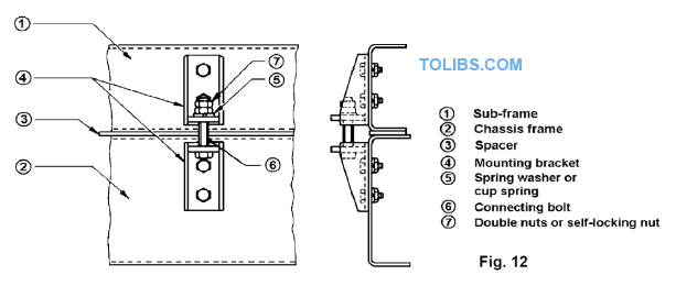
The use of mounting brackets to secure the sub-frame is preferred to U-bolts. If a highly rigid body such as a tank body or closed van body is to be mounted, it is strongly recommended that spacers be used in combination with mounting brackets (Fig. 12). Sufficient spring washers should be used with the connecting bolt. Install the mounting brackets to the chassis frame using bolt nut or rivet attachments at sufficient intervals. Do not weld.
LOCATION PLATES
The sub-frame cannot be securely mounted to the chassis frame using locating plates only. When employing locating plates use U-bolts or mounting brackets. Closely align the front of the sub-frame with the chassis frame using the U-bolts or mounting brackets (Fig. 12). Do not use locating plates for mounting a body having a high centre of gravity or concentrated load. Never use a locating plate for sub-frame mounting of a tank body, dump body, concrete mixer body, van body, etc. Locating plates are not recommended for vehicles operating on rough or winding roads.
COMBINATION WITH CHASSIS FRAME
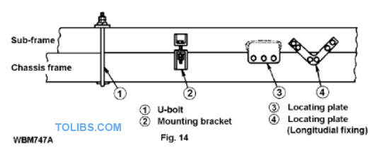
To be effective, the sub-frame must be securely attached to the chassis frame. “U-Bolts”, “mounting brackets”, “locating plates”, etc. are normally used to connect the sub-frame to the chassis frame (Fig. 14). Never affix flanges directly to each other by welding or by bolt-nut attachment.
“U-Bolt” Mounting
A simple method that is frequently used for attaching the body is U-bolts. This is not a recommended method for body mounting because:
- The load is carried on the top flange, not the web.
- The runner stiffens the frame thus reducing the flexibility along part of the frame length.
- The U-bolts holding the runners are often over tightened causing the frame flange to buckle. Once buckled, the flanges have their strength greatly reduced.
- When the metal spacers are positioned between the top and bottom flanges to stop the flange buckling, local stiffening occurs with resultant loss of flexibility.
- Fixing of the body relies on friction and high clamping forces, with no positive location. However tight the Ubolts are when fitted, they work loose and the body is then free to slide on the frame.
- Spacer shrinkage and wear over a period of time can occur and the body mounting becomes loose. Often Ubolts are over tightened at this time to prevent recurrence and frame distortion results.
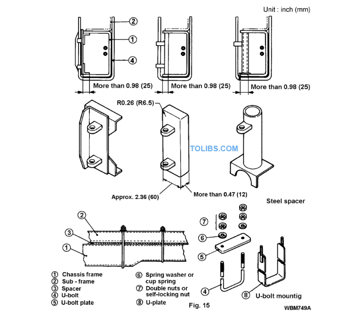
If U-bolt mounting is to be used, then installation must satisfy the following conditions:
- The frame (particularly flanges) must not be distorted. If the vehicle does not have a box type frame, metal spacers must be inserted between the top and bottom flanges of the chassis frame rail to prevent distortion when the U-bolts are tightened. The spacers should be secured in place by the U-bolts as shown in Fig. 15.
- The body must be located fore and aft on the frame and prevented from moving during violent braking by the use of at least four (4) location plates. A location plate must be located at the front and rear of the body on both sides of the vehicle.
- A minimum of three (3) U-bolts per side of the chassis shall be used with the maximum pitch spacing of 1750mm. Installation of U-bolts must conform to the following:
- Lock the nuts.
- Install the U-bolt vertically to the frame.
- Do not install a U-bolt in a tapered portion of the frame (where the web changes in width).
- Minimum U-bolt diameters shall be:
- Bodies up to 2 tonne capacity - 12mm
- Bodies over 2 tonne capacity - 16mm.
- Class 4.6 steel U-bolts are recommended.
Preventing Fore-and-Aft Movement
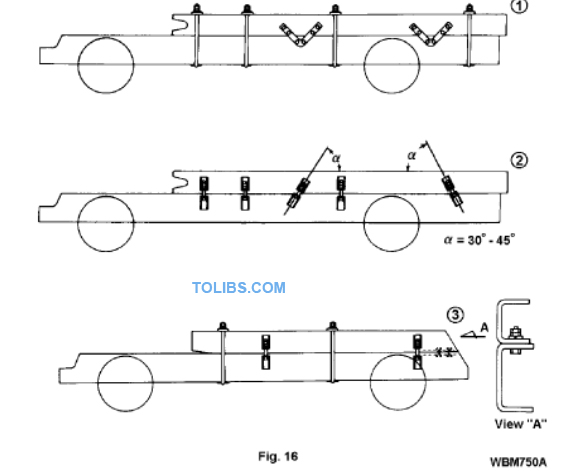
U-bolts and vertically installed mounting brackets do not prevent fore-and-aft movement of the sub-frame. To reduce the possibility of fore-and-aft movement use locating plates as shown in Fig. 16. The frame flanges of dump trucks having a short rear overhang, can be connected at the rear end using bolts and nuts. See Fig. 16-(3).
Note: VSB 6 section J requires, “The body must be located fore and aft on the frame and prevented from moving during violent braking by the use of at least four outrigger brackets or fishplates (i.e. location plates). A bracket or fishplate must be located at the front and rear of the body on both sides of the vehicle”.