UD TRUCKS GWE370 Power Steering Pump
Power steering pump for UD TRUCKS GWE370
Integral hydraulic ball and nut power steering
Worm
Both the radial and the axial rollerbearings are mounted in the cover. Worm Shaft with grooved channel for ball circulation, is mounted in the cover and loaded with the threaded ring.
Piston
The valve bush which accommodates the valve spool is pressed into the cross bore hole. The underside of the piston is machined as a gear rack, which engages in the toothed segment of the sector shaft. The steering nut and the finger passes into the longitudinal bore hole of the piston, thus establishing the connection with the valve spool through the worm. Depending on the version, the valve is centred by means of the centring springs or the bending bar.
Steering nut
Longitudinal bore hole for the worm engagement with grooves for the ball circulation are provided. The hole on the external diameter is milled and ground for accepting the finger, which engages in the cross bore hole of the valve spool. This establishes the connection to the worm by means of the ball chain between the steering nut which depends on the selection of the corresponding type of theball. The steering nut is mounted in the piston, play-free, between the two roller bearings. Adjustment iscarried out by turning the threaded ring which is secured on the open side of the piston.
Housing
The housing has integrated passages for thepressure and the return lines, and a built-in pressure limiting valve. Oil passages which are required within the steering system are arranged as bore holes in the housing, housing cover/plate or in the piston. No external connecting lines are required dueto this design.The housing has mounting holes and machined surfaces for securing the steering gear box on the mounting bracket of the vehicle.
Sector shaft
The sector gearing is cut with a flat angle to the shaft axis, in order to facilitate the serviceadjustment in the axial direction. The center tooth is shaped more convex, so that the re-adjustment can be carried out in straight ahead position (SAP). Since this is the area where the greatest amount of wear occurs, without the following gear teeth, both the left and right getting jammed.
The forces in the axial direction are taken up by means of an adjustment screw. The screw is held into the bore hole of the sector shaft, play-free and passes through the threading in the housing cover.Adjustment in axial direction is carried out by utilizing this thread pitch and locking is done by means of a lock nut.
Housing cover
The component houses the adjustment screw for supporting the sector shaft and two built-in adjustable valves for limiting the pressure atthe wheel lock. The valves are pushed open, by the cam of the sector shaft in the predetermined position at left or right lock. This enables the pressurized oil to flow from the corresponding side of the cylinder chamber to a reduced required pressure ofapproximately 30 to 35 bar.The device is described asHydraulic steering limiters.
Integral hydraulic ball and nut power steering, description
Spool valve, neutral position
in order to obtain the hydraulic support during the steering of the vehicle, the spool valve must be moved out of the neutral position.
The spool valve is held in the neutral position by means of a centring spring or the bending bar depending on the version. Steering forces must therefore be applied in order to overcome this initial setting.
Piston resistance
The piston which is positively connected with the sector shaft and the steering wheels, offers resistanceto rotation. The steering nut is therefore rotated by the worm and the ball chain during the steering process, thus overcomingthe initial setting of the centre spring or the bending bar. The pressurized oil flowing into the gearbox housing from the engine driven pump is then routed into the chamber, fromwhich the steering procedure is hydraulically supported.
Oil flow
The oil flows in from the housing side into a longitudinal groove of the piston and beneath the valve. Oil also flows into a longitudinal groove of the same size, on the opposite side in order to assist for the pressure compensation. It then reaches, by means of cross bore holes at the front surfaces of the valve pistons which are separated from the chamber by means of the seals.
In the neutral position of the valve, the oil flows to the centre of the valve piston after first flowing through the forward and the return edges. From there the oil flows up through the corresponding holes into an opening of the piston. The oil is then drained for the return motion.
Cut-off pressure
By operating the valve, the side of the piston which is under pressure is separated from the return side and the opposite side of the piston which is connected to the return flow. The spool valve is equipped with two feed-back pistons (reaction components), which have the task of making the valve movement from the neutral position more difficultdepending on the oil pressure. The activating forces on the steering wheel increases proportional to the forces which are applied to the wheels.
Steering units which only require a proportional increase of the steering force only up to a predetermined oilpressure are equipped with cut-off hydraulic reaction components (feedback piston).
The spools which are inside the feedback piston, ensures that after reaching the cut-off pressure the forces on the steering wheel, will only increase insignificantly.
Feedback piston (Hydraulic reaction)
They are the floating piston mounted in the bore hole of the valve spool. They are, however, held axially and secured by connecting them with the retaining plates. The outer front areas of the two pistons are continually under pressure, while only one of the internal front surfaces is under pressure in the working position of the valve. The same applies for the front surface in the bore holes of the valve spool. In this way, no force occurs which tries to push the valve spool to the neutral position. This property is described ashydraulic reaction.
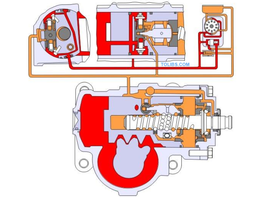
Overview
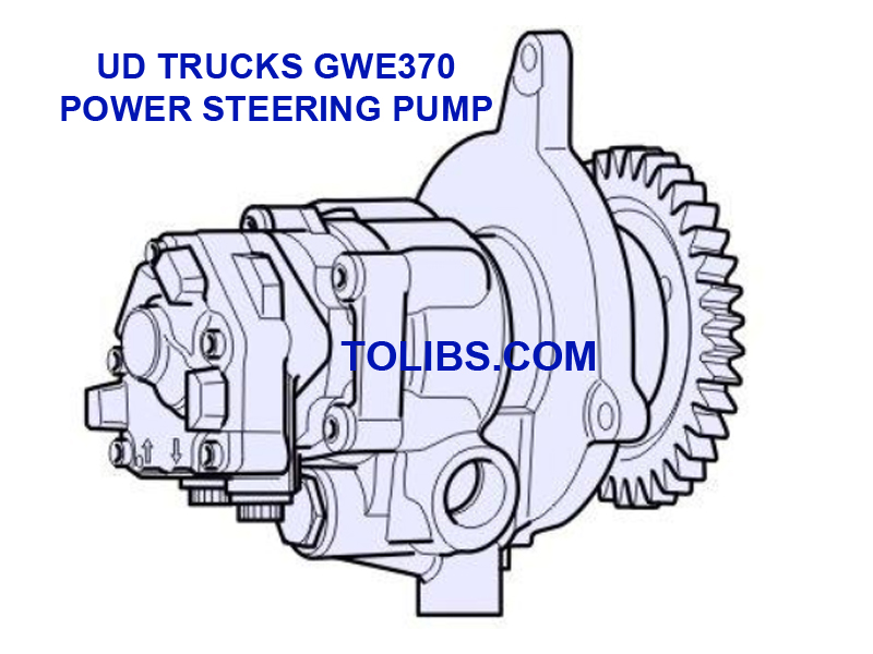
The below illustration, is the section view of a ball and nut power steering gear with the vane pump connected to it, and steering valve in the neutral position. Centring of the steering valve by bending the bar.
Sectional view
- Bending bar
- Worm
- Piston
- Housing
- Valve spool
- Reaction component
- Driver
- Vane pump with flow control valve
- Oil reservoir
- Pressure relief valve
- Cover
- Angular contact ball bearing
- Threaded ring
- Threaded ring
- Steering nut
- Balls
- Sector shaft
Design
The steering housing(4)contains the control valve, a complete mechanical steering gear, and is at the same time the operating cylinder of thepiston(3). The worm(2)and the steering nut(15)are connected by an endless chain of balls. The balls(16)return through the re-circulating tube. The steering nut is maintained clearance-free against the axial thrust by means of the two anti-friction bearings. The control valve is installed across the piston(3). This valve is composed of valve spools and two fixed reaction pistons. Driver(7)fitted on the steering nut, fits snugly into the bore of the valve spool. The piston(3)and the sector shaft(17)are positively connected by a gearing. Due to a special tooth shape on the sector shaft, their axial adjustment is possible. This ensures clearance-free operation in the straight ahead travel range.
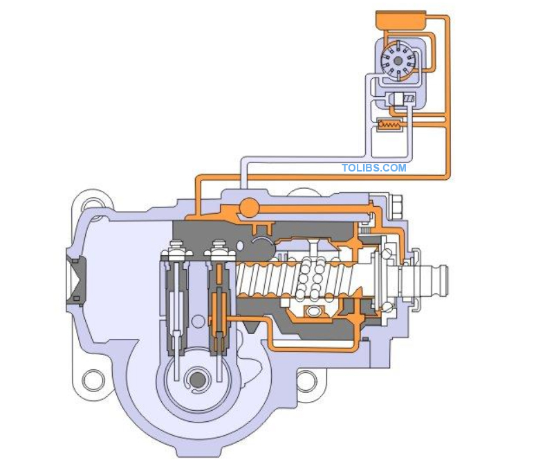
Operation
In neutral position of the valve, the oil pressure in the right and the left cylinder chambers is balanced. By moving the valve spool from the neutral position, a pressure difference is produced between the left and the right cylinder chambers.
The piston(3)will receive more oil pressure on oneside, and the hydraulic power assistance is operative.The valve is actuated by the rotation of the steering wheel or by the force which comes from the road wheels, act through the sector shaft(17)and piston(3)on steering nut(15)and worm(2).
Any rotation of the worm means an axial movement of the output shaft. This operation causes the valve spools to be moved by the finger on the steering nut. Consequently the pressure oil is now supplied to only one of the two cylinder chambers. The piston assiststhe worm rotation. A bending bar or a pressure spring (according to steering gear version) arranged within the steering nut and the valve spools. The operation is assisted by the hydraulic reaction pistons. They are floating mounted in bores of the valve spool, and secured against the axial movement by the locking plates.
The outside faces of the two reaction pistons are permanently pressurised with oil, whereas only oneeach of those inside is pressurised in operating position of the valve. Likewise, onlyone of the two faces in the bores of the valve spool are pressurized with the oil. This causes a force trying to return the valve spool to the neutral position. This process is calledhydraulic reaction.
Oil flow
Oil, after flowing through the supply and return flow control edges to the middle of the valve spool and through the bores to the right and left cylinder chamber. It goes through the respective bores to a recess on the piston top, from there back to the oil tank.
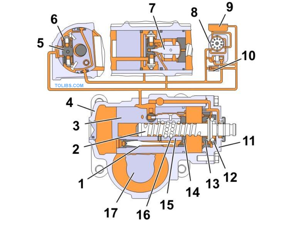
Valve in operating position
Whenthe steering wheels are turned clockwise and the valve spool moved to the right, pressure oil gets into the right cylinder chamber, wherein the left cylinder chamber is connected to the return flow.
Hydraulic steering limiter
This unit reduces the hydraulic power assistance byreducing the oil pressure. The point of response can be adjusted to any drop arm travel. The hydraulic steering limiter protects the wheel stops, steering linkage and the pump from excessive and unnecessary loading at the minimum turning radius. They also contribute to a long service life of the entire steering system.
Hydraulic steering limiter, operation
Figure shows the method of operation of the steering limiting valves. The two valves are installed in the housing cover of the steering gear. When thesector shaft is rotated, they remain shut until the cam on the face of the sector shaft hits one of the valve spools, lifts it up, thus opening the valve. This provides a connection between the highly pressurised cylinder chamber and the oil return circuit.
The pressure in this cylinder chamber drops and the hydraulic power assistance is reduced considerably.The consequence is that the steering wheel can be turned on, up to the wheel stop only under increased manual effort.
Power steering pump
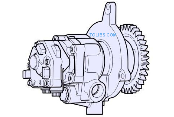
The pump is engine driven. The vane pump is a standard pump and is driven when the engine is running.It is a gear driven type, wherein the same drive shaft is used to the drive fuel pump. The pump has a maximum pressure of 150 bar which is determined by the steering gear, and has a maximum flow of 25 l/min.
Power steering gear
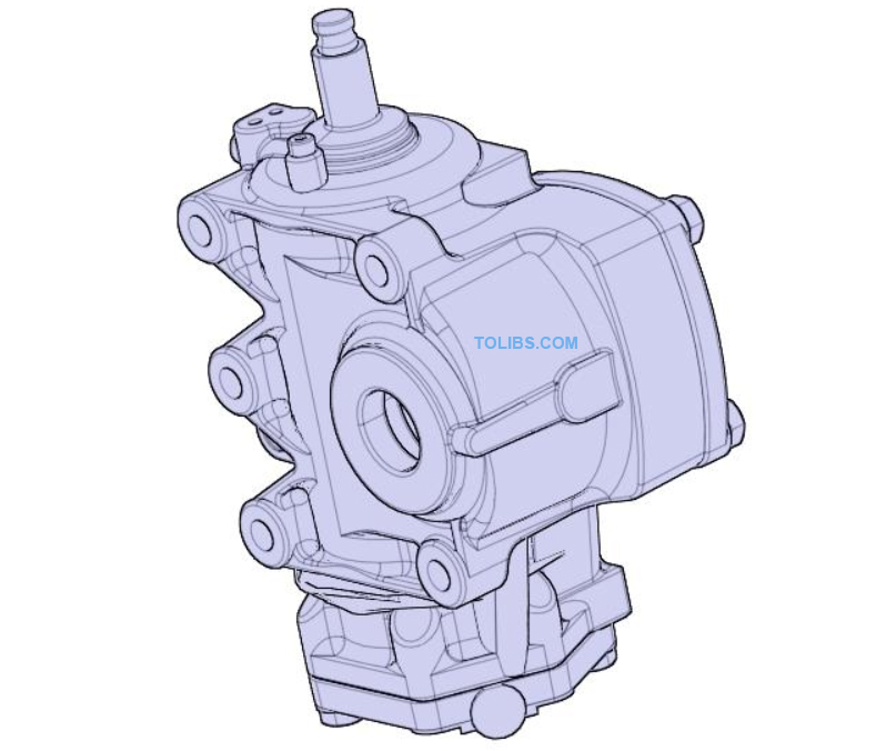
The power steering gear used is ZF8046, PSS single model. The relief pressure is 150 bar. The steering gear is designed for the single circuit steering systems with the integrated pressure relief valve. The steering gear is designed, with automatically adjustable hydraulic steering limiter to limit the pitman arm angles. The steering gear is provided with an automatic bleeder. Read for UD Trucks Kuzer Specifications Document