Holden Engine Troubleshooter Reference Manual
BEFORE OPERATING THIS UNIT, PLEASE READ THIS MANUAL AND ANY APPLICABLE SCANNER AND SAFETY MANUALS.
Every effort has been made to ensure that the information in this manual and software is accurate. The right is reserved to change any part at any time without prior notice. No responsibility is taken for any technical or printing errors that might occur in this manual or software.
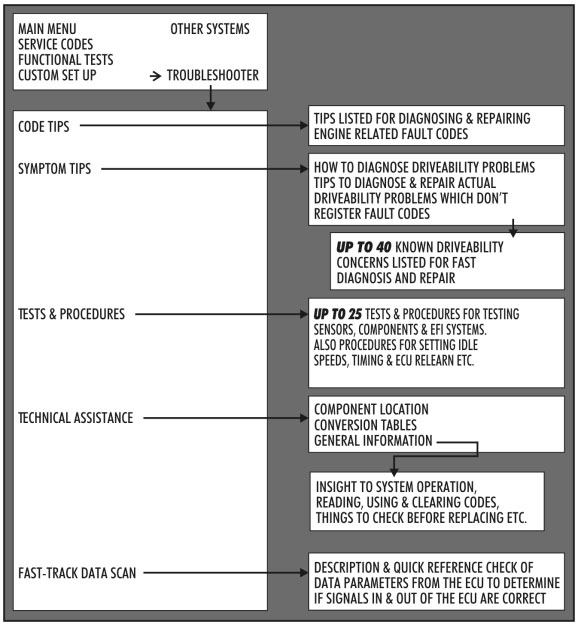
About the Fast-Track Troubleshooter System
Snap-on’s Fast-Track Troubleshooter is a unique time saving diagnosis tool which compliments the Snap-on Scanner. They are used in unison to diagnose and repair EFI related problems. The Troubleshooter incorporates known faults & repair tips, component testing & technical assistance to reduce the down time of diagnosis, therfore saving you time and money. This product is researched and made in Australia for Australian Vehicles. Information is researched from throughout Australia from a large network of technical sources with vast knowledge of product.
The Reference Manual supplied in this kit contains additional information to support many Troubleshooter tips when special instructions, specifications, pinouts and wiring diagrams are needed as indicated by the Scanner.
IMPORTANT: The Fast-Track Troubleshooter system contains information on the most common code problems and driveability complaints on the above vehicles. It does not, however, contain information for every possible code and every possible problem that could occur in all vehicles.
Using Troubleshooter Effectively
The checks in each Troubleshooter tip begin with the most likely cause of a problem or with the tests that should be made first. The checks then progress through other possible causes and tests. All checks in a tip are common causes of a problem or important basic tests, and the most important are listed first. For the most effective use of the Troubleshooter tips, follow the checks in the order in which they are given.
Many checks in the Troubleshooter tips with refer you to references in this Troubleshooter Manual. Consult the references as directed by the tips on the Troubleshooter. Trying to use the references by themselves may cause you to miss important information or to perform some test or adjustment out of sequence.
CAUTION:
During procedures in the Troubleshooter the vehicle’s ignition switch will be required to be switched OFF (eg: for disconnecting connectors etc). This will cause the communication between the Scanner and vehicle to drop out. Sometimes the Scanner will read ‘No Communication’ or drop completely out and sometimes it will still show Troubleshooter information. Note if Troubleshooter information remains on screen, any data parameters shown will be those prior to switching ignition off and will not change due to no ignition power. Ensure ignition is on and vehicle’s PCM is communicating whenever checking any data parameters.
Begin with the basics
The Fast-Track Troubleshooter tips deal with automatic transmission electronic systems and controls. Many tips also contain directions to check fuel, ignition, and other electrical components. As a general rule, basic fuel system, ignition, and electrical tests, as well as a thorough inspection, should be made before performing pinpoint tests on electronic components.
Always ensure that the following systems and components are in proper operating condition:
- Battery condition
- Electrical connectors and wiring harnesses
- Vacuum lines and connectors
- General engine mechanical condition
- Brakes and differential assemblies
Troubleshooting Trouble Codes
Trouble codes should be diagnosed and serviced in a basic order: First, hard codes for currently present problems; followed by soft, or memory, codes for intermittent problems.
GM vehicles transmit codes in numerical order from the lowest to the highest. This is basically the order in which they should be serviced, with current codes being diagnosed before history codes. Code 51 and some other 50-series codes are the exceptions to this general rule. Code 51 for many GM vehicles indicates a PROM fault and should be serviced before other codes. Other 50-series codes that relate to PROM or PCM problems also should be diagnosed before other codes.
To distinguish between a current (hard) code and an intermittent (soft) code on most GM vehicles, clear the codes from PCM memory. Then drive the vehicle and watch for the code to reappear. If it reappears immediately or soon, the code usually indicates a hard fault. If the code does not reappear quickly, it was probably a soft code, indicating an intermittent problem. Some late-model GM cars also have a code history section which shows up to the last four fault codes logged with a history of when they occurred. Refer to ‘Reading, using and clearing codes’ in the Troubleshooter Technical Assistance General Information section.
General Reference
General circuit testing (voltage drop testing)
In most cases, measuring the voltage at various points in a circuit will tell you more about the circuit integrity than measuring the circuit resistance (ohms). A good circuit consists of the supply voltage, a load, and a ground. The load should be activated when current passes through it. A load is any electrical component, such as a lamp, a motor, a solenoid, or a relay. Most electrical circuits also include a fuse on the supply side to protect the load in the event of a short or power surge. Typically, mechanically-switched circuits, such as headlamps and wiper motors, have a switch on the supply side of the load. Electronically-switched circuits such as a TCC solenoid or an EGR solenoid, are usually ground-side switched. Remember, many switches actually energize a relay which, in turn, activates a circuit.
To determine if a circuit is good, check the supply voltage to the load, and check the ground. Figure 1 shows you how to test the supply voltage. Connect the positive (+) DVOM lead to pin A of the load, and the negative (-) DVOM lead to chassis ground. With the switch closed, the DVOM indicates a good supply voltage (13.00 volts) at pin A of the load. This typically indicates that the supply side of the circuit is good. It also indicates that the fuse is not blown. If the fuse was blown, the DVOM would indicate zero volts on the supply side of the circuit.
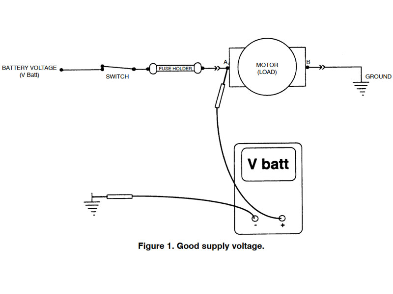
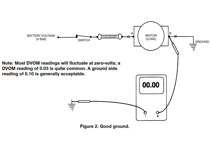
Figure 2 on the next page shows you how to test the ground side of the circuit. The DVOM indicates a good ground (0.00 volts) at pin B of the load, with the switch closed. This typically indicates that the ground side of the circuit is good. (Most DVOM readings will fluctuate at zero volts; a DVOM reading of 0.03 is quite common. A ground side reading of 0.10 is an accepted reading.)
Usually, the fastest and easiest way to check a circuit is to start at the load. In general, there are only six basic types of electrical problems that can affect automotive electrical circuits:
- No supply voltage
- An open ground
- A voltage drop on the supply voltage side
- A shorted lead
- A voltage drop on the ground side
- An open load
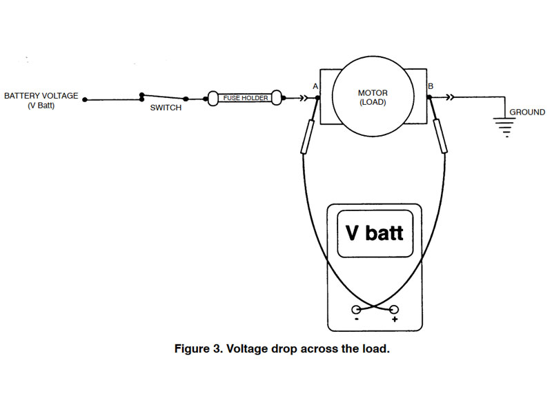
Voltage Drop Across The Load
In some cases it may be preferable to actually measure the voltage directly across a load. This may be because you suspect a poor connection, corroded terminals, or a specific open or shorted component, or simply because a known good ground is not near the portion of the circuit you are testing. Resistance can be high in long thin wires, in poor connections, and in corroded terminals. Therefore, wires, poor connections, and corroded terminals can sometimes “load” a circuit.
To measure the voltage drop across a load, connect the positive (+) DVOM lead to the supply side of the load, and the negative (-) DVOM lead to the ground side of the load, figure 3. In a normally operating circuit, most of the supplied voltage is dropped across the load. If there are two or more loads in a circuit, the voltage drop is divided in proportion to the resistance of each load. That is, the voltage drop across each component should add up to the total supply voltage.
Diagnosing Circuit Problems
Table 1 describes the symptoms, probable causes, and likely solutions for a circuit that is switched ON, but not operating properly. For a circuit that is switched OFF, but is still running, use a DVOM to probe between the load and the switch. Always start as close to the switch as possible. After isolating the problem to a specific segment of the circuit, unhook the circuit at that point to confirm that the circuit stops running. Always test the entire circuit (supply side and ground side) after fixing a problem.
Table 1. Circuit switched ON, but not operating properly. (All DVOM readings are referenced to battery ground, or a good chassis ground, separate from the circuit being tested.)
| Supply Side | Ground Side | Probable Cause | Likely Solution |
| V batt | 0.00-volts | Bad device or connections to device | Check for loose or corroded connector;if OK, replace component. Always test the entire circuit (supply side and ground side)after fixing a problem. |
| V batt | V batt | Open ground circuit | Use DVOM to probe circuit between ground side of component and ground source.Open circuit is located between adjacent test points having different readings.Always test the entire circuit (supply side and ground side) after fixing a problem. |
| 0.00-volts | 0.00-volts | Open supply circuit | Use DVOM to backprobe circuit between supply side of circuit and the supply source.Open circuit is located between adjacent test points having different readings. If fuse is open, check for a short to ground in section of circuit between load side of fuse and supply side of load. Always test the entire circuit (supply side and ground side)after fixing a problem. |
| V batt | Greater than 0.00-volts,less thanV batt | High resistance ground connection | Use DVOM to probe circuit between ground side of component and ground source.High resistance circuit is located between adjacent test points having different readings. Always test the entire circuit (supply side and ground side) after fixing a problem. |
| Less than V batt, greater than 0.00-volts |
0.00-volts | High resistance power connection | Use DVOM to backprobe circuit between supply side of circuit and supply source. High resistance circuit is located between adjacent test points having different readings. Always test the entire circuit (supply side and ground side) after fixing a problem. |
Note: Most DVOM readings will fluctuate at zero-volts; a DVOM reading of 0.03 is quite common. A ground side circuit reading of 0.10 volts is acceptable.
| Ref. No. | Page | Subject |
| H001 | 9 | VN Model (to Oct 1989) V6 wiring diagram and connectors |
| H002 | 11 | VN Model (from Oct 1989) & VP Model V6 wiring diagram and connectors |
| H003 | 13 | VN Model (to Oct 1989) V8 wiring diagram and connectors |
| H004 | 15 | VN Model (from Oct 1989) & VP Model V8 wiring diagram and connectors |
| H005 | 17 | VR Manual Model V6 wiring diagram and connectors |
| H006 | 19 | VR Automatic Model V6 wiring diagram and connectors |
| H007 | 21 | VR & VS Manual Model V8 wiring diagram and connectors |
| H008 | 23 | VR & VS Automatic Model V8 wiring diagram and connectors |
| H009 | 25 | VS Model V6 wiring diagram and connectors |
| H010 | 27 | VT Model V6 wiring diagram and connectors |
| H011 | 29 | VT Model V8 wiring diagram and connectors |
| H012 | 31 | VX Model V6 connector diagram |
| H013 | 32 | VY Model V6 connector diagram |
| H014 | 33 | V6 Direct Fire Injection (DFI) Power Balance Testing |
| H015 | 34 | Fuel System Diagnosis Using Fuel Pump Current |
| H016 | 35 | V6 Crankshaft Sensor Testing |
| H017 | 37 | Integrator and Block Learn Functions |
| H018 | 39 | Short Term and Long Term Fuel Trim Functions |
| H019 | 41 | 3.8 Litre V6 Ignition Test |
| H020 | 43 | Intake Air and Manifold Air Temperature Sensor Resistance Values |
| H021 | 44 | Knock Sensor Test |
| H022 | 45 | Quad Driver Circuit Test |
| H023 | 46 | 5.0 Litre V8 Coil Resistance Check |
| H024 | 46 | 3.8 Litre V6 Coil Resistance Check |
| H025 | 47 | VN (pre Oct 89) 5.0 Litre V8 Ignition Test |
| H026 | 48 | VN (post Oct 89) to VS 5.0 Litre V8 Ignition Test |
| H027 | 49 | VT 5.0 Litre V8 Ignition Test |
| H028 | 50 | VR Model V6 Manual Transmission EST Check |
| H029 | 51 | VR Model V6 Automatic Transmission EST Check |
| H030 | 52 | VS & VT Model V6 EST Check |
| H031 | 53 | VN, VP V8 Model & VR, VS (manual only) V8 Model EST Check |
| H032 | 54 | VR & VS V8 (auto only) Model EST Check |
| H033 | 55 | VT 5.0 Litre V8 Model EST Check |
| H034 | 56 | VX & VY V6 Model EST Check |
| H035 | 57 | Coolant Temperature Sensor Resistance Check |
PLEASE NOTE WIRING DIAGRAM WIRE COLOURS ARE GIVEN AT THE PCM AND MAY NOT ALWAYS BE CORRECT DUE TO MANUFACTURING CHANGES IN PRODUCTION. ALSO WIRE COLOURS AT COMPONENTS AND SENSORS MAY NOT BE THE SAME AS AT THE PCM. ALL CONNECTORS ARE VIEWED LOOKING INTO FACE OF CONNECTION.