Holden Barina Workshop Service Repair Manual

Holden Barina Antilock Brake System Automated Bleed Procedure
Bleeding the ABS System
Perform a manual or pressure bleeding procedure. Refer toHydraulicBrake System Bleeding. If the desired brake pedal height results are not achieved, perform the automated bleed procedurebelow.
The procedure cycles the system valves and runs the pump in order to purge the air from the secondary circuits normally closed off during normal base brake operation and bleeding. The
automated bleed procedure is recommended when air ingestion is suspected in the secondary circuits, or when the BPMV has been replaced.
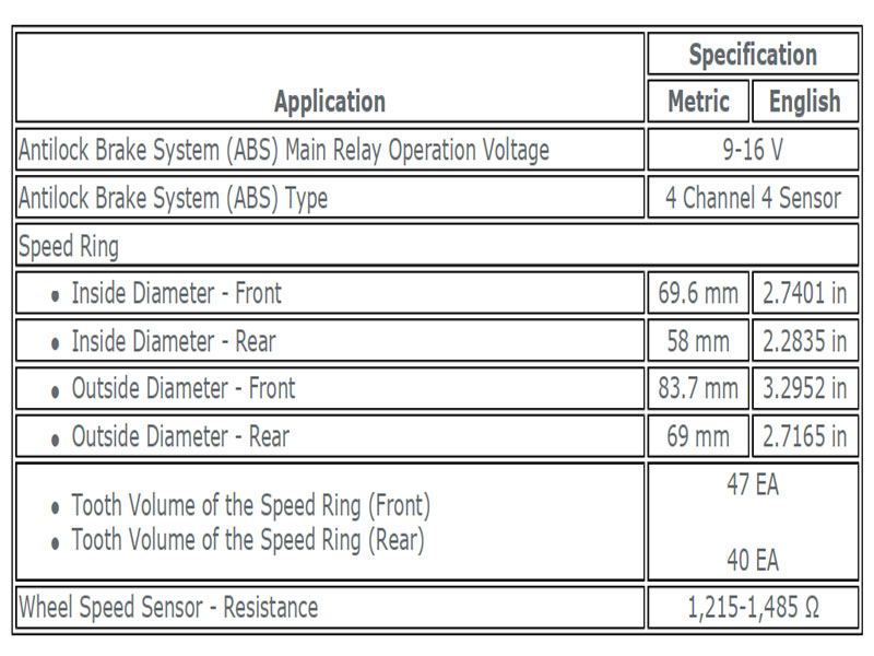
Holden Barina ABS Component Specifications
Holden Barina Automated Bleed Procedure
Caution:The Auto Bleed Procedure may be terminated at any time during the process by pressing the EXIT button. No further Scan Tool prompts pertaining to the Auto Bleed procedure will be given. After exiting the bleed procedure, relieve bleed pressure and disconnect bleed equipment per manufacturers instructions. Failure to properly relieve pressure may result in spilled brake fluid causing damage to components and painted surfaces.
- Raise the vehicle on a suitable support. Refer toLifting andJacking the Vehicle.
- Remove all four tire and wheel assemblies. Refer toTire andWheel Removal and Installation.
- Inspect the brake system for leaks and visual damage. Refer toBrake Pipeand Hose InspectionorSymptoms-Hydraulic Brakes. Repair or replace as needed.
- Inspect the battery state of charge. Refer toBatteryInspection/Test.
- Install a scan tool.
- Turn ON the ignition, with the engine OFF.
- With the scan tool, establish communications with the EBCM. SelectSpecial Functions. Select Automated Bleed from the Special Functions menu.
- Bleed the base brake system. Refer toHydraulicBrake System Bleeding.
- Follow the scan tool directions until the desired brake pedal height is achieved.
- If the bleed procedure is aborted, a malfunction exists. Perform the following steps before resuming the bleed procedure: If a DTC is detected, refer toDiagnosticTrouble Code (DTC) List-Vehicleand diagnose the appropriate DTC. If the brake pedal feels spongy, perform the conventional brake bleed procedure again.Refer toHydraulicBrake System Bleeding.
- When the desired pedal height is achieved, press the brake pedal in order to inspect for firmness.
- Remove the scan tool.
- Install the tire and wheel assemblies. Refer toTire andWheel Removal and Installation.
- Inspect the brake fluid level.
- Road test the vehicle while inspecting that the pedal remains high and firm.
Brake Pressure Modulator Valve Assembly Replacement
Removal Procedure
- Disconnect the negative battery cable. Refer toBatteryNegative Cable Disconnection and Connection.
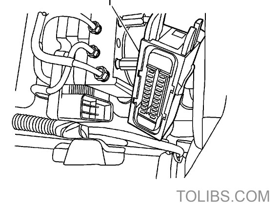
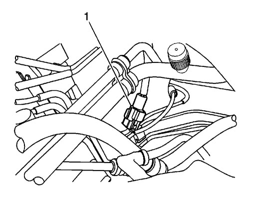
- Disconnect the electronic brake control module (EBCM) connector (1).
 Note:Take care not to allow air into the hydraulic unit or into the brake pipes from the master cylinder. If air getsinto the hydraulic unit, it will require a bleeding procedure using a
scan tool programmed for the ABS 5.3 system. As long as no air enters the hydraulic unit, a simple bleeding procedure is all the system will require. - Remove the brake pipes from the brake pressure modulator valve (BMPV) assembly.
- Plug the brake pipes.
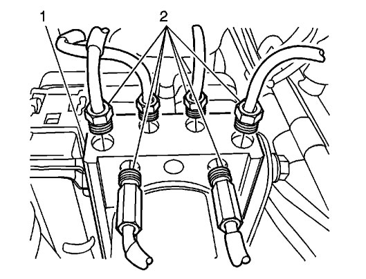
- Loosen the mounting nuts (2) on the BPMV assembly (1).
- Position the brake pipes aside far enough to allow for lifting the BPMV assembly from the mounting bracket. It may be necessary to loosen the brake pipes on the master cylinder to
allow for moving those pipes out of the way. - Remove the BPMV assembly from the mounting bracket.
Brake Installation Procedure
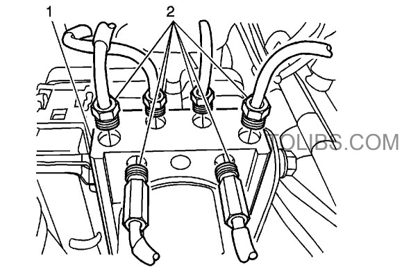
- Install the BPMV assembly (1) into the mounting bracket. Secure with two nuts (2) and tighten to15 N·m (11 lb ft).
- Remove the plugs from the brake pipes and connect the brake pipes to the BPMV assembly (1) and tighten to22 N·m (16 lb ft).
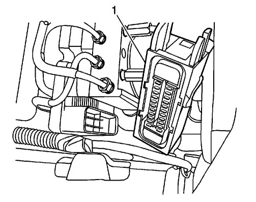
- Connect the EBCM connector (1).
- Connect the negative battery cable.
- Bleed the brake system.
- Perform theDiagnosticSystem Check-Vehicle. Refer toHydraulicBrake System Bleeding.
- Refer to Control Module References for programming and setup information.
Holden Barina Front Wheel Speed Sensor Replacement
Removal Procedure
- Disconnect the negative battery cable. Refer toBatteryNegative Cable Disconnection and Connection.
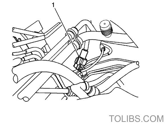
- Disconnect the front wheel speed sensor electrical connector (1).
- Raise and suitably support the vehicle. Refer to Lifting andJ acking the Vehicle.
- Remove the wheel. Refer to Tire and Wheel Removal and Installation.
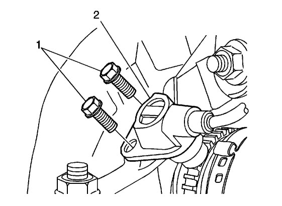
- Remove the bolts (1) and the front wheel speed sensor (2) from the steering knuckle.
Installation Procedure
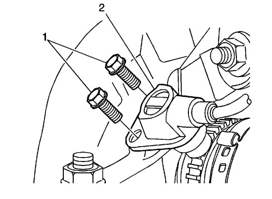
- Install the front wheel speed sensor (2) to the steering knuckle. Secure it with the bolts (1)and tighten to8 N·m (71 lb in).
- Install the wheel. Refer toTire and Wheel Removal and Installation.
- Lower the vehicle.
- Connect the front wheel speed sensor electrical connector (1).
- Connect the negative battery cable. Refer to Battery Negative Cable Disconnection and Connection.
Holden Barina Knock Sensor Replacement Removal Procedure
- Disconnect the battery negative cable.
- Disconnect the electrical connector at the knock sensor.
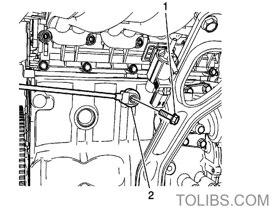
- Remove the knock sensor retaining bolt (1) from the engine block.
- Remove the knock sensor (2).
Holden Barina Knock Sensor Replacement Installation Procedure
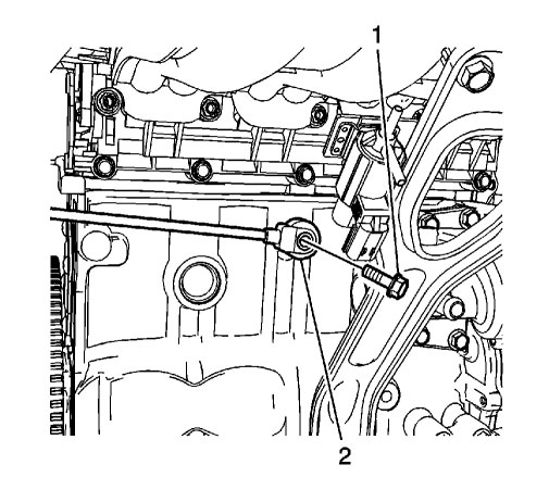
- Install the knock sensor (2).
- Install the knock sensor retaining bolt (1) and tighten to20 N·m (15 lb ft).
- Connect the electrical connector at the knock sensor.
- Connect the battery negative cable.
Holden Barina Throttle Body Assembly Replacement Removal Procedure
- Disconnect the battery negative cable.
- Remove the air cleaner assembly.
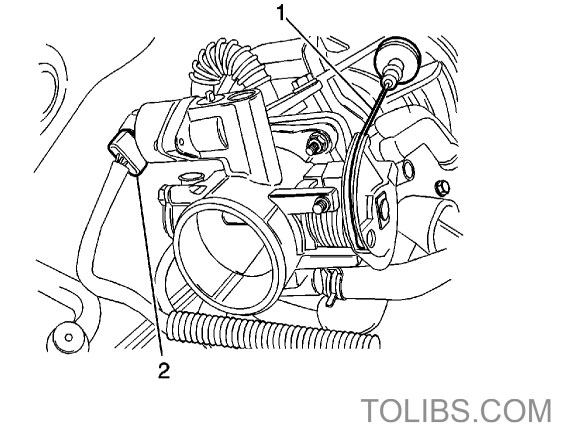
- Disconnect the throttle cable (2).
- Disconnect the throttle position sensor (TPS) and IACV connectors (1).
- Disconnect the coolant inlet and outlet hose.
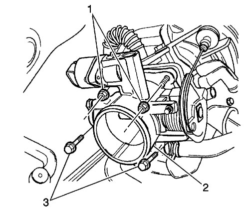
- Remove the throttle body retaining bolts (3) and nuts (1).
- Remove the throttle body (2) with the gasket.
Holden Barina Throttle Body Assembly Replacement Installation Procedure
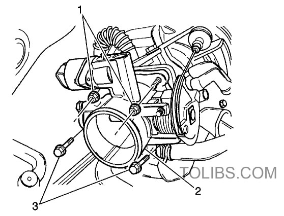
- Install the throttle body (2) with the NEW throttle body gasket.
- Install the throttle body retaining bolts (3) and nuts (1) and tighten to10.5 N·m (7.7 lb ft).
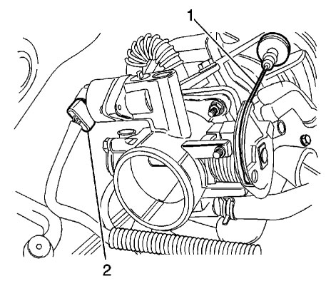
- Connect the throttle cable (2).
- Connect the throttle position sensor (TPS) and the IACV connectors (1).
- Connect the coolant hose.
- Connect the battery negative cable.