Service, Repair and Workshop Manuals for Holden Astra

PULSAR N13 Series, ASTRA LD Series
1.6 and 1.8 Liter 1987 – 1991
INTRODUCTION
This Service and Repair Manual covers the Australian manufactured Nissan Pulsar (hatchback) and Vector (sedan) N13 Series 1(J87 - 91 and the Holden Astra LD Series 1987 - 1989. Two engines were available: a 1.8 liter engine with multi-point fuel injec-tion, and a 1.6 liter throttle body injected engine. The engines are similar having single overhead camshafts and computer controlled fuel injection and ignition control. There was a choice of three speed automatic or five speed manual transaxles. A viscous coupling limited slip differential was introduced from July 1989 to the five speed manual transaxle models of the Pulsar Q and Vector SSS. Disc brakes are fitted at the front of all models, while the rear brakes are either discs or drums.
All models are equipped with independent coil spring suspension. Steering can be by either manual or power assisted rack and pinion. This manual includes information ontrouble shooting, lubrication and maintenance, specifications and the removal, installation and overhaul of com-ponents which are considered to be within the scope of the average, well equipped home mechanic.
Certain repair jobs covered in thismanual require the use of special equipment not normally found in a home tool kit. When such equipment is required, the equipment and its function is brought to the users attention underneath the heading forthat component. Some jobs, such as automatic transmission overhaul, should he left toan authorized dealer or a specialist who has the extensive knowledge and equipment required. In these cases, the removal and installation procedures are fully covered, enabling the unit to be removed for repair or a reconditioned unit to be installed.
Reference in the manual to the left and right hand sides of the vehicle are from the point of view of someone standing at the back of the vehicle and looking forward. Inexperienced operators should not attempt a service or repair operation before completely reading the appropriate section (or other sections which may be referred to) in the manual.
VEHICLE IDENTIFICATION AND GENERAL SPECIFICATIONS
1. VEHICLE IDENTIFICATION
When purchasing spare parts or when registering or insuring a vehicle, it may be necessary to quote various vehicle identification codes. The location of these codes are as follows:
The Engine Number is stamped on the front face of the engine block below No. 4 spark plug. The Chassis Number is stamped on the bulkhead above and to the right of the brake booster. The Vehicle Identification Plate is located on the bulkhead to the left of the MAP sensor and contains codings relating to body style, engine capacity, model, transaxle type, engine number, paint, trim and build date.
The Compliance Plate contains information on the vehicle make, model, month and year of manufacture, chassis number, seating, capacity and the Australian Design Rules (ADR) with which the vehicle complies. This plate is affixed to the bulkhead above and to the left of the brake booster.
The Tire Placard, which is located on the inside of the glove compartment, contains information on the tire size, rim size, tire pressure and load ratings.
GENERAL REPAIR PROCEDURES
SEIZED FASTENERS
Seized bolts, nuts or screws should first have a liberal amount of penetrating oil applied. The fastener should be left for a period of time to allow the oil to penetrate and soften the corrosion which is causing the binding.
Often, a sharp hammer blow to the head of the fastener can dislodge the corrosion and permit it to be loosened. An impact driver, which can be fitted with a socket or screwdriver bit, can be used to loosen a seized fastener.
Another method is to heat the component in which the fastener is seized. However, extreme caution should be exercised when heating aluminum alloy components as the melting point is much lower than that of steel.
If the above methods fail to free a seized nut, carefully hacksaw through one side of the nut until it can be split. Care should be taken that the threads of the bolt or stud are not damaged. Should a bolt or stud break below the surface of the component, it will be necessary to use a screw extractor to remove the remaining part. Follow the screw extractor manufacturers instructions.
2. GENERAL VEHICLE SPECIFICATIONS
Length:
- Pulsar...4 030 mm
- Astra hatchback ...4 035 mm
- Vector ...4215 mm
- Astra sedan...4 255 mm
Width:
- Nissan ... 1 640 mm
- Holden ... 1 655 mm
Height ... 1 380 mm
Wheelbase...2 430 mm
Wheel track:
- Front ... 1 435 mm
- Rear ... I 430 mm
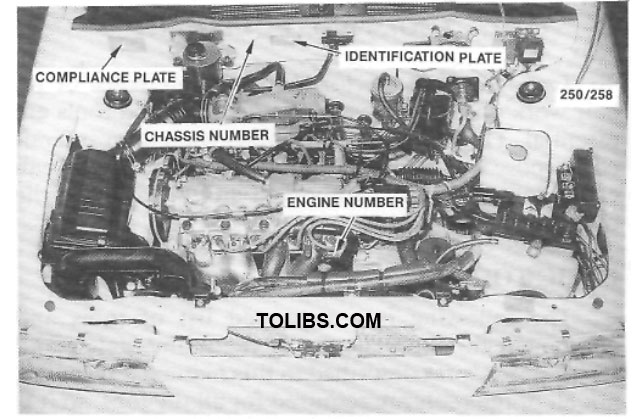
View of the engine compartment showing the location of various vehicle identification information.
Minimum ground clearance:
- Nissan.. 128 mm
- Holden.. 110 mm
Turning circle kerb to kerb .. 10..8 m
Fuel tank capacity:
- Nissan.. 47 liters
- Holden.. 50 liters
Towing capacity:
- Without trailer brakes.. 400 kg
- With trailer brakes .. 900 kg
| L/100km (City) | L/100km (Highway) | |
| Manual transaxle | 8.5 | 6.6 |
| Automatic transaxle | 9.0 | 7.2 |
*The fuel consumption information is based on tests made according to Australian Standard 2877. The actual fuel consumption will depend on many factors including driving habits, vehicle condition and equipment and the prevailing conditions.
GENERAL INFORMATION
1. TOOLS AND EQUIPMENT
To successfully perform any maintenance or repair work on a motor vehicle, suitable hand tools are essential. The use of tools for other than their intended purpose or the use of incorrectly fitting tools can cause damage to the component and/or injury lo the operator.
BASIC TOOL KIT:
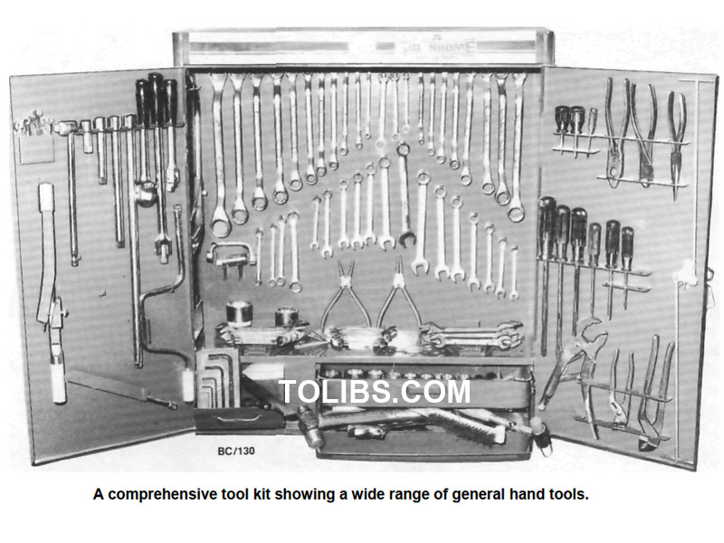
The following is a suggested list of tools and equipment for the majority of the maintenance and repair procedures described in this manual. Of course, not all of the tools are required for all the jobs, so it is wise to purchase tools on an 'as needed' basis.
- Set of open ended spanners.
- Set of ring spanners.
- Set of socket spanners.
- Spark plug spanner.
- Assorted bladed screwdrivers.
- Assorted Philips screwdrivers.
- Assorted pliers — combination, long nose, multigrip, vice grip, snap ring (internal and external).
- Assorted adjustable spanners.
- Ball pein hammer.
- Cold chisels.
- Pin punches and centre punch.
- Assorted files.
- Scraper.
- Feeler gauges.
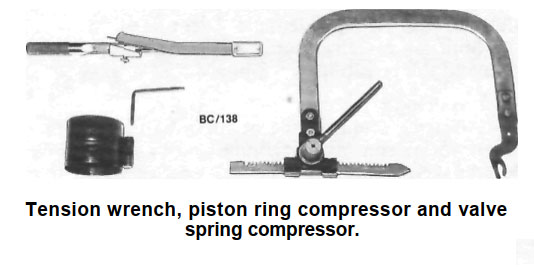
- Torque wrench.
- Hydraulic jack.
- Chassis stands.
- Car ramps.
- Grease gun.
- Oil can.
- Oil gun.
- Oil filter removal tool.
- Funnel.
- Containers for draining oil and washing components.
Assorted test equipment - dwell tachometer, digital multimeter, timing light and test lamp.
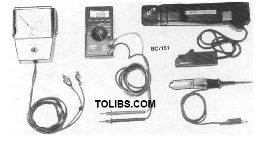
- Inspection lamp.
- Test lamp.
- Tachometer.
- Timing light.
- Digital multimeter.
- Piston ring compressor.
- Valve spring compressor.
- Micrometer - inside, outside, multi range.
- Vernier calipers.
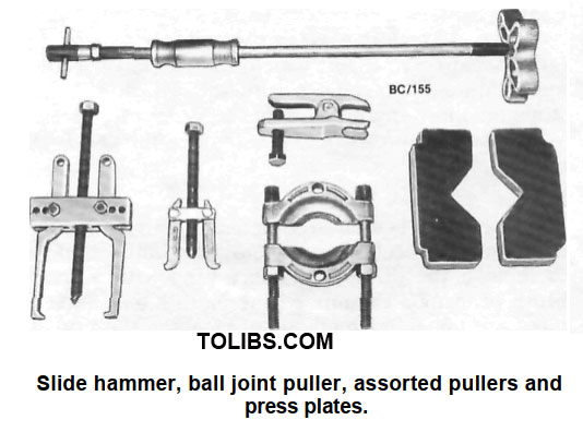
- Assorted pullers.
When purchasing tools, it is sound advice to select the highest quality that can be afforded, as the working life of cheaper tools is often very short.
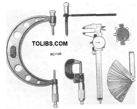
Assorted measuring devices - inside and outside micrometers, vernier calipers, wire gauges and feeler gauges.
Ensure that the tools are suitable for the system of bolt and nut sizing on the vehicle. The range of vehicles covered by this manual use metric sizes.
TOOL CARE
To ensure the longest possible life for hand tools, it is important that time be spent maintaining them. At the conclusion of each job. all tools used should be washed thoroughly in kerosene or similar cleaning solvent. Ensure that all dirt and grease is removed, particularly from tools with moving parts such as pliers and adjustable spanners. The tools should then be wiped dry with a clean cloth.
Measuring devices should be given particular attention as their accuracy can be affected if not properly maintained. Feeler gauges should be kept clean at all times and the blades should be wiped with an oily cloth after use to prevent rusting.
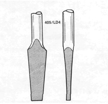
Views showing the correct tip profiles for a bladed screwdriver. Bladed screwdrivers should not be ground to a sharp point.
If tools are to be stored for any length of time, it is good policy to wipe them with an oily cloth. Bladed screwdrivers should be checked for damage to the tip. If necessary, the tip can be returned to its original profile by careful grinding. Do not grind screwdriver tips to a sharp point.
Hammer heads should be secure on their handles and should be regularly checked for cracking or other damage. Chisels and punches should be checked for damage or 'mushrooming' of the head. Any faults should be rectified by grinding.
Hydraulic jacks should be regularly checked for fluid leaks. Chassis stands and car ramps should be checked for damage and cracks. Any equipment that is suspect should not be used.
STORES

Oils and greases are available in handy pack size for do it yourself lube jobs.
For routine maintenance, stores of automotive oils, greases and additives should be kept on hand. The following is a suggested list.
- Engine oil.
- Brake fluid.
- Manual transmission or automatic transmission
- oil = automatic transmission oil is also used in
- the power steering system.
- Rear axle oil.
- Cooling system corrosion inhibitor/antifreeze.
- Chassis grease.
- High melting point grease, for hub bearings etc.
- Penetrating oil or spray.
- Kerosene or similar cleaning solvent.
- Methylated spirits.
2. SAFETY
Safety when working on a motor vehicle is basically a matter of commonsense. Some safety precautions to prevent personal injuries are as follows.
Raising a Vehicle
Always jack a vehicle on firm, level ground and at the specified jacking points. Ensure that the wheels remaining on the ground are fully chocked. After raising the vehicle, place chassis stands underneath and allow the weight of the vehicle to rest on them. Do not use bricks, blocks of wood or similar material.
NOTE: Never work under a vehicle which is only supported by a jack.
Electrical System
Always disconnect the negative battery terminal when working on any electrical components. Avoid wearing metal watches, rings and chains which may short across live terminals. As battery gases are explosive, keep naked flames and sparks clear of the work area. When connecting and disconnecting jumper leads, use extreme caution to avoid sparking.
Electronic Ignition Systems
Electronic ignition systems produce dangerous high tension voltages in both the primary and secondary circuits which can be fatal. Exercise extreme caution when working on or near any ignition system components. Do not disconnect high tension leads while the engine is running.
Work Area
Do not run the engine in a confined space. Ensure that the work area is adequately ventilated. Spilt oil or water should be cleaned immediately to avoid the possibility of slipping.
Fuel System
Always disconnect the negative battery terminal when working on any fuel components. Do not smoke. Keep naked flames and sparks clear of the work area. Do not siphon fuel using the mouth. Use a hand pump or suitable siphon. Do not attempt to repair a fuel tank by welding it. This is an extremely hazardous procedure and should be entrusted to a specialist.
Cooling System
To avoid scalding, use caution when releasing the radiator cap on an engine which is at normal operating temperature. Turn the cap anti-clockwise to the first stop and allow any pressure in the system to release. When the pressure is released, remove the cap from the radiator.
Brakes
As asbestos is used in some brake lining material, avoid inhaling brake dust. Do not use compressed air to remove the dust. Gentle brushing with a small brush or using a vacuum cleaner with a hose attachment are the safest methods of cleaning the brakes. The above precautions also apply to the clutch plate lining material.
LUBRICATION AND MAINTENANCE
HOW TO GREASE AND OIL CHANGE
- Run the front of the vehicle onto car ramps and stop the engine. Chock the front wheels.
- Raise the rear of the vehicle and place chassis stands under the rear jacking points.
- Clean around the engine sump drain plug.
- Place a drain tin under the engine sump, remove the engine sump drain plug and allow the engine sump to completely drain.
- Check that the sealing gasket on the sump plug is in a serviceable condition.
- When the engine sump has completely drained, install and firmly tighten the sump drain plug. Wipe around the plug after installation.
- Place the drain tin under the oil filler, remove the oil filter using a filter removal tool and allow the residual engine oil to drain. Smear the scaling ring of the new filter with engine oil and lighten the filter by hand as per the instructions supplied with the new filter.
- Remove the level checking plug from the
NOTE: It is best if the vehicle is kept as level as possible to avoid false readings when checking the lubricant levels.
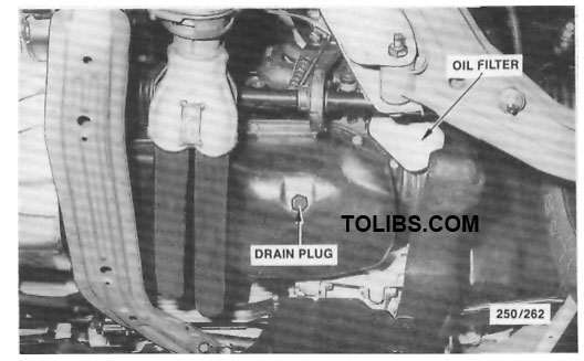
Location of the engine sump drain plug.
Wheels should be cleaned regularly of dirt and mud.
is allowed to build up it will affect the balance of the wheel and may cause vibrations and uneven tire wear. The alloy wheels are coated with a clear protective finish. Do not use abrasive cleaner, polishing compounds, steel wool etc. when cleaning the wheels. Only mild soap and warm water are recommended. Alloy wheels are particularly susceptible to corrosion damage particularly if exposed to salt water. Alloy wheels being relatively soft in comparison to steel are easily scuffed, however, this will not affect the serviceability of the wheel. Where heavy damage has been sustained to the wheel it should be renewed. Buckling or cracking of an alloy wheel cannot be repaired.