Mazda RX-8 Rotary Engineering 36DCD Installation Guide
INSTALLATION GUIDE 36 DCD DUAL WEBER
CONVERSION KIT
- PART NO. 6140-13-2370 (12A ENGINES-'74 ON)
- PART NO. 6140-13-4560 (13B ENGINES-ALL)
CONGRATULATIONS! You have purchased the finest induction system available for the rotary engine. Not only will this conversion provide increased horsepower but also improved driveability as well as increased gas mileage during steady state driving.
Although it is not necessary to be an automotive mechanic to successfully install this kit, it is presumed that the installer possesses a basic mechanical ability. Properly installed and adjusted, this Weber conversion will give years of trouble-free enjoyment.
This, or any carburetion increase for that matter, will not work on the Mazda rotary engine without the use of a header system to replace the restrictive thermal reactor or catalytic converter. Therefore, this installation guide assumes that headers have been previously installed.
As with any modification, maximum performance can only be achieved when the entire engine is is good working order. For this reason, it is advisable to perform a thorough check of your engine electrical system before installing this kit and perform a tune-up (to stock specifications) if necessary, replacing any worn parts.
PRELIMINARY SET-UP
Using the linkage kit installation guide as a reference, per form the preliminary set-up on the workbench as follows:
- Install carbs on manifold (make sure there is a gasket between the carb and phenolic insulator) with float bowls toward the front using nylock nuts and thin 8mm washers provided.
- Thread 5/16” nuts onto rod ends leaving %” of threads below nut. Screw one rod end into rear hole of rear manifold boss and the other rod end into the only hole in the front boss. Tighten down lock nuts.
- Install throttle cable bracket with the two 5/16” bolts and lock washers provided in the remaining holes of the rear boss.
- Assemble linkage as follows:
- a. Slide linkage rod into the rod ends with welded lever arm forward of cable arc.
- b. Slide linkage spacer onto rod behind rear rod end.
- c. Install lever arm on rod behind spacer as illustrated (do not tighten).
- d. Install oil injection lever.
- e. Center rod between oil injection lever and rear lever arm. Be sure the rod turns easily and leave about 1/32” end play.
- f. Line up the rear lever arm with the welded lever arm and tighten. (Leave oil injection lever loose for adjustment later.)
- g. Extend the adjustable linkage rods to exactly 4-1/8” center to center.
- h. Install adjustable rods between lever arms and carbs. Tighten lock nuts.
- Back out idle speed screws (Fig. 2, Pg. 6) in carbs until throttle plates are fully closed.
- Install throttle return spring from small hole in arc to small hole in throttle cable bracket.
- Turn in idle speed screws until they touch then an additional % turn to crack the throttle plates open.
INSTALLATION ON CAR
- Disconnect negative battery cable
- Drain cooolant NOTE Not all Mazdas have a radiator drain petcock, however, all are equips with a 14mm dram plug on the lett side of the motor at the bottom of the intermediate housing
- Remove entire air cleaner assembly.
- Disconnect brake vacuum hose from intake manifold.
- Disconnect oil injection tubes and oil injection rod at the carburetor. Disconnect fuel hoses and remove from car. Disconnect choke and throttle cables. (RX-7: also discon nect the 5 vacuum lines that run from the base of the carb. Disconnect hot start cable Disconnect air conditioning valve vacuum line, if equipped.) Disconnect any other hoses or wires still connected to carb.
- Using a 12mm socket, remove the six nuts and washers securing intake manifold to engine and remove manifold/carb assembly.
- Remove all smog valves and piping from top of engine (RX-7: also remove vacuum valves on firewall [Calif models only] as well as hot start control motor on rear of left shock tower.
- Remove oil injection rod and put aside for later use.
- Install Weber carb/manifold assembly with provided gasket using original nuts and washers. NOTE: Due to the possibility of resurfaced side housings the manifold mounting holes are oversize, so while tightening the mounting nuts, pull up on the manifold to ensure proper port alignment.
- Slip oil injection tubes onto carburetors and into stock tubes as shown in Figure 1 (kinked tube to rear carb, straight tube to front carb). If the fit is loose, a piece of wire twisted around the rubber connection is a good idea to prevent them from slipping off.
- Hook up stock throttle cable as shown in linkage kit installation guide. If necessary, adjust pedal stop (inside car at pedal) to provide enough cable. Make certain there is a slight amount of slack in the cable so that throttle plates will fully close. Check operation making sure that throttle plates open fully.
- Install choke cable as shown on reverse of linkage installation guide. Use shorter cable on rear carb. Before tightening cable clamps at carb choke levers, adjust the cables to allow about 1/16" slack when choke is fully in. Check operation.
- Bend oil injection rod removed earlier, using pattern provided on back of linkage installation guide. Reinstall rod allowing 1/32" to 1/16" free play before lever on oil metering pump becomes engaged as shown below. Tighten oil injection lever on linkage rod.
The fuel return line (smaller of the two is now used as a second fuel supply line for the Webers. This is easiest done on the RX-7 by installing the Rotary Engineering Dual Fuel Pump Mounting Kit (Part No. 6330-13-6117) and two electronic fuel pumps (Part No. 6330-13-6150 ea ). On other models, a fuel line tee can be installed right after the pump to supply fuel to both steel lines. Be sure to plug the unused return line back to the fuel tank. The high flow capability of the Webers require a higher flow fuel pump than stock. Two of the above mentioned pumps work fine, however, any high flow electric pump will work. Because Grose-Jet inlet valves have been installed in the Webers, they are capable of handling up to 6 psi fuel pressure, however, 3 V? psi is ideal for best operation.
STARTING ENGINE
- Idle speed screws have been adjusted to 1/4 turn in and ignition timing should be stock.
- Turn the idle mixture screws (Figure 2) all the way in, then back out one turn each.
- NOTE: Carbs are shipped with mixture screws removed.
- Start engine. You may need to use some choke.
- The engine should idle, possibly roughly, but it should idle. If it won’t idle at all. turn the idle speed screws in another 'A turn each and let the engine warm to operating temperature.
ADJUSTING IDLE MIXTURE
Turn the mixture screw of one carburetor in until the engine starts to hunt severely (idle speed unstable) then very slowly back it out until that rotor runs smoothly. Then back out an additional 1/8th turn. By doing this several times with each carb, you should obtain a very smooth idle and both carbs should be nearly identical in adjustment. Both mixture screws should be about one turn out. (On a sound engine when the idle mixture is correct, turning the screws in V? turn should cause severe hunting or engine stalling and turning out 1/2 turn should cause the engine to lope badly.)
INSTALL AIR FILTERS
Place air filter bases on carb tops (base with hose fitting goes on rear carb). Fit PCV hose to fitting on rear air filter. Install air horns over air filter bases and secure with 5mm flange nuts provided. Saturate filtron elements with oil provided (squeeze out excess) and fit over supporting screens. Install element assemblies and filter tops to carbs. Secure with springs provided as shown in Figure 2. NOTE: Except while adjusting carbs, never operate a rotary engine without air filters. Even a small particle of dirt can severely damage the housings.
IGNITION TIMING
The vacuum advance system of the distributor is not used with the Weber set-up. Only the built-in centrifugal advance system is used. For optimum performance the ignition timing should be set with a timing light and a good ear.
Troubleshooting guide
When properly set up. Weber carburetors are virtually troublefree and should not need adjusting any more often than the stock carb. The only external adjustments on the carbs are idle speed and mixture. Any running above idle is controlled only by the internal components and should never require adjustment unless the horsepower capabilities of the engine are changed (i.e., porting is performed).
This troubleshooting guide is provided to assist you in locating the source of and correcting any problems you may encounter with your dual Weber conversion. This troubleshooting guide assumes that there is nothing wrong with the engine or ignition system as we are referring to carburetion problems only.
THE ROTARY ENGINEERING 36 DCD WEBER CARBURETOR
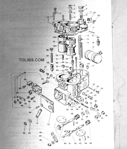
This exploded view of the Rotary Engineering 36 DCD carb is not provided as an incentive to tear your carburetor apart. It is provided for reference use only. The major components are itemized below. If you wish to overhaul your carbs we have available a very good Haynes Manual (Part No. 6430-77-3930) on Weber carburetors which includes a section on the DCD carb.
- 1. Carb top
- 9. Fuel inlet screen
- 9A. Fuel inlet fitting
- 9B. Oil injection fitting 13/14/15/20. Accelerator pump assembly
- 16. Grose-Jet inlet valve
- 17. Float
- 21. Acc. pump intake valve
- 22. Idle jet
- 26. Primary main jet
- 26A. Secondary main jet
- 29. Idle speed screw
- 31. Mixture adjusting screw
- 38. Carb body
- 41. Secondary throttle shaft
- 42. Primary throttle shaft
- 51. Throttle control lever
- 56. Choke cover assembly
- 68. Choke piston
- 70. Pump jet
- 72. Primary venturi (choke)
- 72A. Secondary venturi (choke)
- 73. Primary auxiliary venturi
- 73A. Secondary auxiliary venturi
- 74. Primary air corrector jet
- 74A. Secondary air corrector jet
- 75. Primary emulsion tube
- 75A. Secondary emulsion tube