Mazda Rotary Engine Workshop Manual 1971 and 1981
Mazda ROTARY ENGINE Workshop Manual by Kenichi Yamamoto
Preface
Only about 20 years have passed since Felix Wankel devised the principle of the Wankel engine, which consists of two-lobe epitrochoid with inner envelope. Since then, the basic construction has been improved from the DKM to the KKM type, with steady development continuing in the area of mechanical design, such as engine specifications, dimensions and component constructions, as well as in other areas such as materials and manufacturing techniques. Today, Wankel engines are being put to practical use by two companies in Japan and three in Germany.
Historically, the development of prime movers, including the reciprocating engine, has proved to be an extremely difficult task, requiring a great deal of research and experimental work, due to the fact that development of this sort involves a multitude of highly complex, interrelated problems. On top of this, the necessary refinements are extremely time-consuming since they are based on careful obser vation and evaluation of the various phenomena and test data observed and gathered during actual testing, processes which often involve tedious trial and error methods.
We can see, then, that the present NSU-Wankel engine was put into practical use with a comparatively small amount of research and, at the same time, within a relatively short period of time. It gives every indication of harboring tremendous potential for development and growth. In fact, rotary engines are so attractive, as potential prime moving mechanisms in the next generation, that engineers the world over had been busily putting forth all sorts of ideas as to their possible application. On the other hand, it is also a fact that none of them had materialized because of a variety of technical problems. This fact in itself should be sufficient indication of the technological difficulties encountered in the development of rotary engines. As things stand today, the NSU-Wankel is the only rotary engine in successful practical use, and as such is now being studied on a worldwide basis. The author feels that the material presented here on the rotary engine should prove of great interest to the students and general public who are concerned with the engineering of internal combustion engines.
This book is entitled “Rotary Engine”, however, its scope is limited to the description of the NSU-Wankel engine developed jointly with NSU, based on Felix Wankel’s invention.
I should like to stress again that this engine is still in the development stage, so the data presented here are illustrative of concepts and ideas. It would be the author’s pleasure if this book could be of any help to the readers in better understanding the NSU- Wankel engine. The entire contents of this book were written in close and intensive cooperation with the following people working in the engineering, research, design, testing and material sections of the Rotary Engine Research Division of Toyo Kogyo Co., Ltd. The author would like to express his sincerest appreciation to all of them.
- The Concept of Rotary Engines: Kazuhiko Moriyama.
- Basic Dimensions: Yasuo Tatsutomi.
- Basic Construction: Yasuto Terazawa, Hiroshi Ohzeki.
- Gas Sealing: Yutaka Hirose.
- Cooling: Kazuo Maekawa.
- Lubrication: Kaneaki Takagi.
- Engine: Vibration Yasuyuki Morita.
- Ignition: System Masao Shibagaki.
- Engine Performance and Combustion: Nagao Takeuchi, Masaharu Shimoji.
- Multi-rotor: Engine Kazuhiko Moriyama.
THE CONCEPT OF THE ROTARY ENGINE
History of the Development of Rotary Piston Engines
Rotary engines, which have attracted great attention since the appearance of the NSU-Wankel engine, have a long history. The original idea is said to have come from the rotary piston type water pump which dates back to the 16th century.
Since that time, it has been generally agreed that the simple function of a rotary piston gives it a definite advantage over the combined mechanism of a reciprocating piston and a crank. Because of the simplicity, various types of rotary engines have been proposed. As a matter of fact, the rotary mechanism has long been in practical use in the field of volumetric type piston machines such as pumps, blowers and compressors, which are in a reverse relationship to the internal combustion engine. However, in internal combustion engines, the only rotary piston mechanism to become practical so far is the NSU-Wankel engine.
Among the greatest obstacles encountered in creating the rotary engine, compared to the reciprocating engine, were:
- Difficulty in assuring seal tightness of the working chamber under high pressure.
- Incomplete establishment of optimum intake and exhaust systems satisfactorily matching the thermodynamic operating cycle of gas. Felix Wankel had long been interested in rotary engines of all kinds, including those used in compressors and pumps. He began to conduct investi gations to sort out the known types, and to lay them out systematically. He went into technical cooperation with NSU and in early 1954 he presented his ideas on a rotary engine, which were accepted as having good possibilities. This actually marks the beginning of the joint research program of NSU and Wankel.
This new rotary engine can be classified into the following two types, by the characteristics of the piston (rotor) motion:
- Single rotation machines (Drahkolbenmaschinen: DKM)
- Planetary rotation machines (Kreiskolbenmaschinen: KKM)
With both types, the contour of the inner surface of the outer casing is composed of a peritrochoid. Inside this casing is an internal piston, the apex of which always slides along the peritrochoid. The operating principle is that the relative rotation of the internal piston against the casing causes the space between the walls of the two to change continuously.
In the early stage of the NSU-Wankel research effort, the single rotation type was the first studied. Preliminary investigation was conducted on a compressor application and the feasibility of volume change of the working chamber was confirmed, with the type in which the outer casing and the internal piston rotate in the same direction around their respective axes.
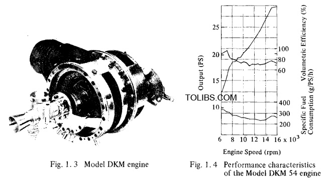
In 1957, after further development of this compressor version, a prototype of the rotating piston type engine was ' successfully tested. This was called the DKM 54 type, and it had a volume of 125cc for each of the three working chambers. Although the test result (Fig. 1. 4) was encouraging, this type was so complex in structural design that substantial changes in its construction became inevitable before it got beyond the early experimental stage.
In 1958, the basic engine construction was changed to the planetary rotation type, and a series of prototype manufacturing and testing projects were started on the Model KKM 125 engines with 125cc displacement per working chamber and the Model KKM 250 with 250cc displacement.
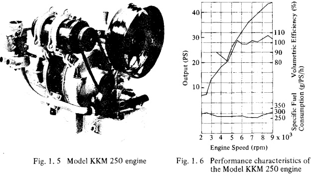

The tests confirmed that this planetary rotation type engine had no critical defect as an internal combustion engine. This planetary rotation type engine is a dynamically reverse version of the single rotation type, in that the center of gravity of the internal piston rotates as it revolves around the center of the output shaft, while the outer casing remains stationary.
Since this change in engine type, further development has resulted in a considerable simplification of the engine construction and improvement in reliability. In fact, it may be said that the basis for the NSU Wankel engine was established by the decision to change to the planetary rotation type construction. Since that time, technical agreements have been made one after another for the commercialization of this type of rotary engine, and extensive development projects are now emerging for gasoline, diesel and hybrid engines, according to the plans set by the companies under license.
Trochoid
When using the so-called trochoidal curves for the configuration of the inner surface of the outer casing and for the internal piston, one of the following three curves is used, drawn with the transfer ratio i=rg/r as a rational number. They are the peritrochoid of Fig. 1. 8, the epitrochoid of Fig. 1. 9 and the hypotrochoid of Fig. 1. 10. Note that the transcendental circumferential curves drawn with the transfer ratio of an irrational number, and the intersecting circumferential curves drawn when the choice of the condition r $ r is improper. Both of them will produce circumferential curves not suitable for the purpose of the rotary piston machines, consequently they are not applicable.
Peritrochoid
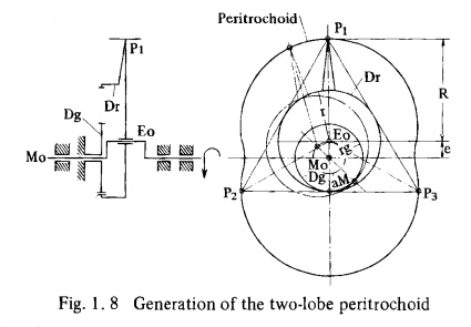
When the revolving circle Dr (radius r) rotates around the outer circumference of a fixed base circle Dg (radius rg), the peritrochoid is defined as the locus of the generating point Pl (the generating radius R) on the extension line of the rolling circle’s radius. The essential conditions for this case are : rg < r ; i = rg/r< 1 ; R > r
Fig. 1. 8 shows the generation of the two-lobe peritrochoid when i = 2 : 3, which is used for the inner surface contour of the outer casing of the NSU-Wankel planetary rotation type engine.
Epitrochoid
When the revolving circle Dr (radius r) rotates around the fixed base circle Dg (radius rg), the peripheral curve, drawn by the generating point P on the revolving circle radius, is called the epitrochoid. General conditions are: rg r i = rg/r 1
The base circle Dg rotates around the revolving circle Dr which is fixed on the opposite plane S. Consider plane S cross-sectioned completely. When the peritrochoid T of band form moves around, the plane S is divided into two regions, one with the cross-sectioning completely removed and the other with the cross sectioning still remaining. The dividing curves of these two regions are envelopes. Curve Ha, the outer border of the peritrochoid T, is the outer envelope, while curve Hi, the inner border of the peritrochoid is the inner envelope. In this case, the corner points I, II and III of these inner and outer envelopes are always in contact with the peritrochoid, so that they do not move radially and therefore can be considered stationary. From these characteristics, it can be presumed that when any of these envelopes (inner or outer) is used as a basis for rotary piston machines, the sealing pieces radially arranged at these comer points can easily follow the movement of the rotor at high revolutions.
illustrates the possible combinations of the trochoid and its envelope when i = 1:2, 2:3, 3:4 and 4:5.
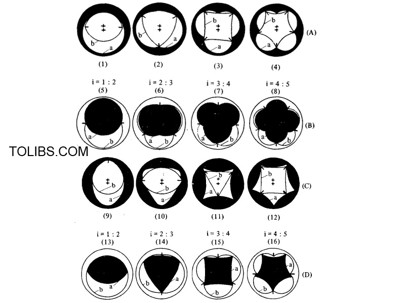
(A) In this series there are the combinations of the arcs of the peritrochoid (a) with lobe number (n) for the inner surface of the outer casing and its inner envelopes of the peritrochoid (b) with n + 1 apex or flank for the internal piston. In this case, a transfer ratio of i = n/n + 1 exists.
(B) This series shows the combinations of the peritrochoid (a) with n = 1, 2, 3 and 4 lobes for the internal piston and its outer envelope (b) for the outer casing.
(C) In this series there are the combinations of the hypotrochoid (a) with n = 1, 2, 3 and 4 flanks and its inner envelope (b). The (D) series is a combination of the hypotrochoid (a) for the internal piston and its outer envelope (b) for the outer casing.
Some of these combinations have been known for some time through patent bulletins. For example, the type using the peritrochoid for the internal piston was patented in Germany under patent No. 156127 by Colley as a steam engine of the rotary piston type. Under English patent No. 583075, B. Maillard employed the hypotrochoid for the internal piston of a compressor.
Another example is the French patent No. 853807 in which De la Vand attempted to apply hypotrochoids to an internal combustion engine. The idea of using the peritrochoid for the outer casing and its inner envelope for the internal piston contour with i = 1 : 2 was first tried by Paul Kirchhoff, and was patented under German patent No. 8689, and research was conducted with this type on Oldham blowers. It is known that Planche & Cie of France has also tried a similar type for compressors and blowers in recent years. It was F. Wankel, however, who first proposed the ideal i = 2 : 3 and 3 : 4 type for internal combustion engines and expansion mechanisms.
As the major component, the eccentric shaft (1) which is the output shaft, supports the rotor (2) through the rotor bearing (6) at the central eccentric ring portion which corresponds to the rotor journal. The internal gear (8) installed at the end of the rotor, mates with the external gear (7) fixed on the side housing (4), constituting peritrochoidal phase gears with the transfer ratio i = 2 : 3.
Therefore, as the eccentric shaft rotates the rotor revolves around the center axis of the eccentric shaft while rotating itself on the eccentric rotor journal. Through this mechanism, the ratio of the output shaft rotation to that of the rotor is set at 3 : 1 and the locus of the rotor apex always slides according to the same singular peritrochoid curve.
The side housings containing the main bearings (5), and the trochoidal housing with which the rotor apex seals (18) come in contact, are bolt tightened. The cooling water flows through the water jacket (13) inside these housings. The inlet for the cooling water is located at the lower part of the rotor housing. The water divides, and the streams flow upward and in parallel, inside the side housings and the rotor housing.
The rotor is oil cooled by lubricating oil, which is= supplied under pressure to the oil passage (10) in the center of the eccentric shaft. Then it flows to the rotor bearing through oil passages located radially in the rotor journal portion, and finally into the hollow chamber inside the rotor. When the oil level inside the rotor is higher than the outer diameter of the stationary draining vane (11), the surplus oil is drained through radial and axial passages which are interconnected. This maintains constant oil level, and thereby eliminates engine vibration due to changes of oil quantity in the rotor.
All of these rotating components, including the eccentric shaft, rotor, bearing and the flywheel (9), are dynamically balanced with the quantity of the cooling oil inside the rotor taken into consideration. Unbalanced weight of the rotor and its journal portion are corrected by holes made near the outer edge of the flywheels on both ends of the eccentric shaft.
The intake and exhaust ports, (16) and (17), and the spark plug (15) with its opening, are located on the trochoid wall. Combustion recesses (19) are provided on the three surfaces of the rotor flank for obtaining proper compression as well as for preventing the division of the operating gas at the two constricted parts of the trochoid at top dead center.
You May Like to see 1975 Mazda Rotary Pickup Workshop Manual Document